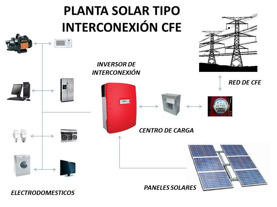
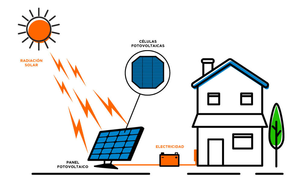
Isolated PV systems do not need a connection to an electrical network and their operation is independent or autonomous from said network.
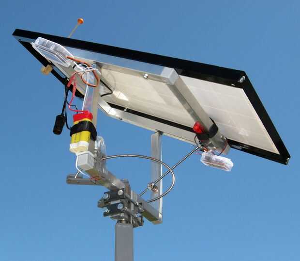
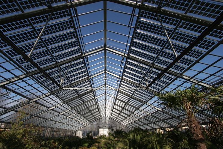
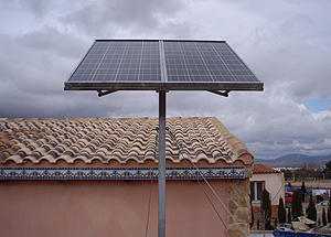
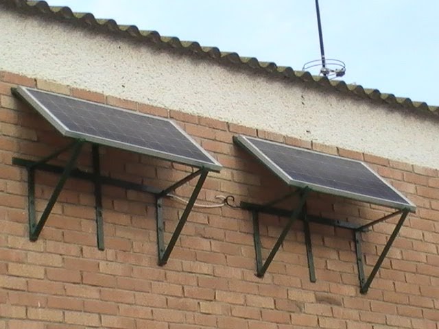
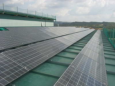
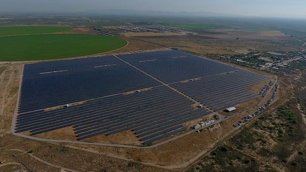
Applications that are currently being implemented the most are small installations for lighting houses that are not reached by the general network, pumping, various agricultural facilities, signaling, hostels, campsites, shelters, summer and weekend chalets.
The criterion followed in isolated PV systems sizing is not so much to produce maximum energy but rather the concept of reliability appears (to ensure the proper functioning of the system, ensuring that failures are minimal).
Sizing an isolated photovoltaic system requires 7 steps:
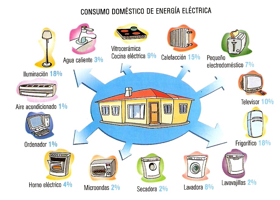
1. Estimation of electrical load (electrical consumption)
We must know power of each element of consumption and the estimated time of use. Normally the calculation is made using W / h as the unit of energy.
To estimate these values we can consult following link
2. Estimation of solar energy available
Hm is the energy in kWh that affects a square meter of horizontal surface on an average day of month m. From the corresponding table the value is obtained in MJ / m2 (mega joules / m2).
The conversion must be carried out and expressed in Wh / m2 or kWh / m2. Being 1 MJ at 277.77 Wh or 0.277 kWh.
To estimate these values we can consult following link
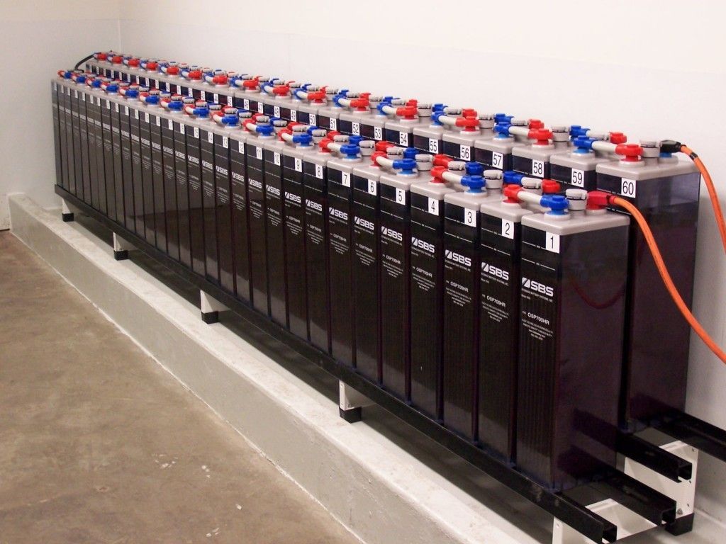
3. Battery sizing
To define accumulator size, you must set N (Days of autonomy). It is the number of consecutive days that in the absence of Sun, accumulation system is able to meet consumption, without exceeding maximum discharge depth of the battery.
Having identified N and knowing the total energy required Et (final electricity consumption) in a period of 24 hours, we are going to calculate the real energy Er that the modules must contribute to the chosen battery (which will have a maximum admissible discharge depth pd).
The daily energy Er must take into account the different losses that exist:
Er = Et / R
Where R is a global factor of installation performance, whose value will be:
R = 1 – [(1-kb-kc-kv) ka. N / pd] – kb – kc – kv
kb: coefficient of battery performance. It varies between 0.05 (if there are no intense discharges) and 0.1 (for more unfavorable cases).
ka: self-discharge coefficient. If the data does not appear on the battery’s technical sheet, it can be estimated at 0.005 (0.5% daily).
kc: loss coefficient in the converter. If the system does not incorporate an inverter, it is zero. It ranges from 0.2 for sine wave inverters to 0.1 for square wave inverters.
kv: coefficient of other losses. It is usually estimated at 0.15 and 0.05 if we have already considered the performance of each device when calculating consumption.
Once R is calculated and Er obtained, we proceed to determine the useful capacity Cu of the battery. The battery must be able to accumulate the energy to be supplied throughout this period:
Cu = Er. N
To go from Wh to Ah, we will divide Cu by the nominal battery voltage (usually 12 V or 24 V).
Now we calculate the maximum nominal capacity C assigned by the battery manufacturer. These capacities will be assigned for temperatures between 20º and 25º C.
C = Cu / pd
With these data, the batteries offered on the market will be selected that most closely approximates the nominal capacity C obtained.
To estimate these values we can consult following link
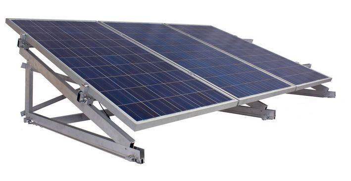
4. Dimensioning of modules area
Energy originating in modules that must reach the accumulator (Er) suffers losses originated by the regulator, which are estimated at approximately 10%; therefore the daily amount of energy to be produced by the Ep modules is:
Ep = Er / 0.9
From the following formula we will calculate the HSP (hours of peak sun or hours of sun at an intensity of 1000 W / m2), starting from H expressed in MJ (1 kWh = 3.6 MJ):
HSP = 1 / 3.6k. H (MJ) = 0.2778 k. H
k is the correction factor for modules inclination according to the latitude of installation location.
H is the average daily radiation of each month expressed in MJ / m2.
To access these values we can consult following link
As we have already said, we must base ourselves on the most unfavorable month and also correct according to area climatological factors (clean atmosphere or mountain area = 1.05; area with pollution = 0.95; area with fog = 0, 92).
The ideal orientation is always towards equator and to determine the inclination we can follow recommendations in PV modules support structure post.
To calculate modules number we will use the following formula:
NM = Ep / 0.9. Pp. HSP
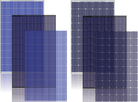
Pp is nominal (peak) power of chosen modules. The most suitable modules combination for the installation will be selected (price, available space, load to satisfy, etc.).
It is multiplied by 0.9 to consider possible additional losses that can cause modules dirt, reflection, etc.
If result is not a whole number, it will be rounded to the higher unit if decimal is equal to or greater than 0.5 and lower if it is less than 0.5.
Knowing the total modules number of PV generator and battery nominal voltage, which coincides with installation nominal voltage, it is possible to determine if it is necessary to group the modules in series and in parallel. The number of modules to be connected in series is calculated as follows:
Ns = VBat / Vm
Where:
Ns modules number in series per branch
VBat nominal battery voltage (V)
Vm nominal voltage of the modules (V)
And the number of branches in parallel to connect to supply the necessary power is given by:
Np = NM / Ns
Where Np is the number of modules to be connected in parallel branches.
5. Specify the controller or regulator
For sizing we can consult Solar charge controller post.
The installation will be dimensioned in such a way that the safety factor corresponds to a minimum of 10% between maximum power produced and that of regulator. The minimum possible number of regulators will be used.
To find the number of regulators Nr we will use the following equation:
Nr = Npp. ip / go
Being:
Npp the number of modules in parallel.
ip the peak intensity of the selected module.
go the maximum intensity that the regulator is capable of dissipating.

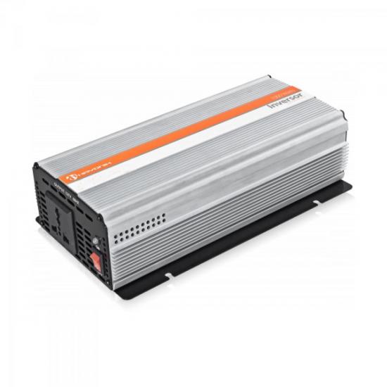
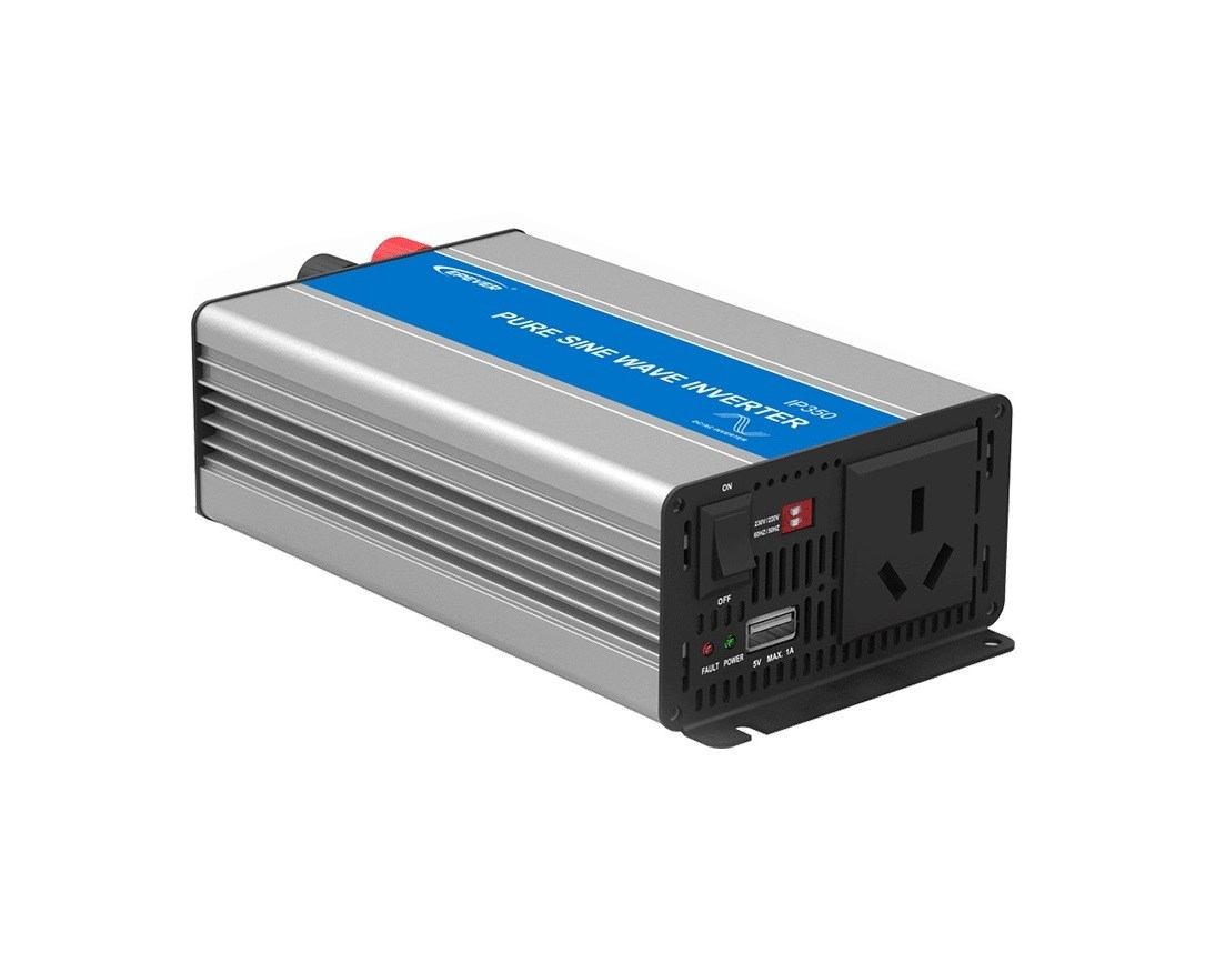
6. Sizing of the inverter
When sizing the inverter, the power demanded by the load made up of AC devices will be taken into account, so that an inverter will be chosen whose nominal power is slightly higher than the maximum demanded by the load.
For inverter sizing if PV systems has AC devices we can consult Solar converter post.
7. Choice of cable section
To select the cable section, the recommendations in the section Other elements (Wiring) post will be taken into account.
The sizing of the wiring constitutes one of the tasks in which special attention must be paid, since whenever there is consumption there will be losses due to voltage drops in the cables.
We can consult Solar wiring post.
This is an extract of contents included in Technical-Commercial Photovoltaic Solar Energy Manual and Sopelia e-learning training.
All you need is Sun. All you need is Sopelia.