Tag Archives: solar energy

Other Components Solar Thermal Energy

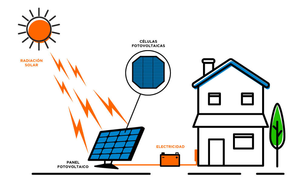
Thermal solar energy systems incorporate components that allow their correct operation and control. Some are mandatory (safety elements) and others are incorporated for better performance and maintenance of the system.

The expansion vessel is one of the essential safety elements for the system to work correctly, since its function is to absorb the expansion of the fluid at the moment it overheats.

Closed expansion vessels are the most widely used in solar thermal systems, since all of them are carried out in a closed circuit.

In this case, it is a hermetically sealed container divided into two chambers, one for fluid (1) and the other for gas (2), separated by a membrane (3) as can be seen in the diagram below.

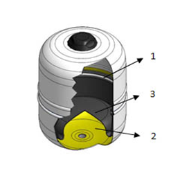
The membrane (high quality synthetic rubber) is flexible and allows chambers volume to be variable depending on each moment needs.

What is intended is to provide an extra capacity to the circuit, which allows it to absorb fluid expansion, so it must be dimensioned to support said expansion in the most unfavorable conditions.

When membrane has expanded to the maximum and the vessel can no longer absorb any more expansion, the circuit pressure will increase as the temperature of the fluid increases, until causing the safety valve to actuate (limit situation).

In principle, the expansion vessel can be located both at the outlet and at the return of the system because, as it is a closed circuit, the fluid expansion will be the same on one side as on the other. Despite this, it is always better to locate all components, if possible, in the cold part of the system for greater durability.

The expansion vessels will preferably be connected to the suction of the pump.

Another important component is the manometer. This element is used to know the pressure value in kg/cm2 inside a pipe or tank.

MANOMETRO I.S.R. M1/4" 6 bar - Industrial llobera

The choice of valves will be made according to the function they will perform and the extreme operating conditions (pressure and temperature).

The nominal pressure PN, expressed in bar or kp/cm2, and the nominal diameter DN, expressed in mm or inches, shall be stamped on the valve body, at least when the diameter is equal to or greater than 25 mm.

The minimum nominal pressure of all types of valves and accessories must be equal to or greater than 4 kp/cm2. The free diameters in the valve seats must correspond to their nominal diameters, and in no case less than 12 mm.

The characteristic valves of a solar thermal energy system are:

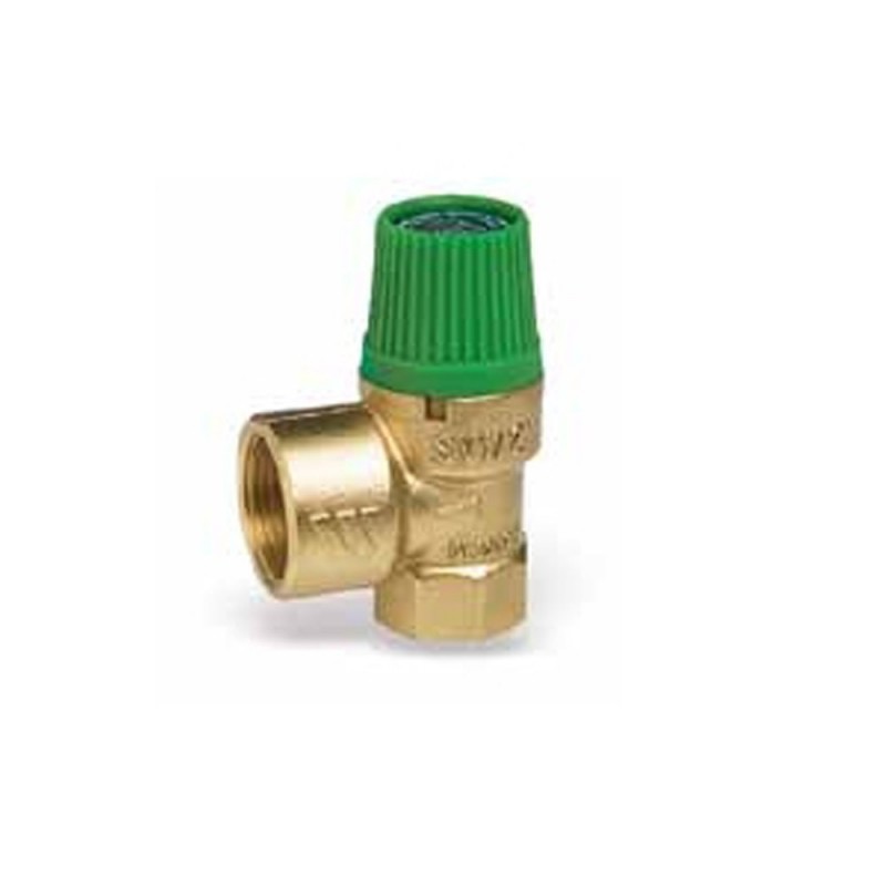
1) Safety valve: due to their important function, they must be capable of deriving the maximum power from the collector or group of collectors, even in the form of steam. Its placement is recommended in all circuits subjected to pressure and temperature variations.
The pressure at which the valve acts (set) allowing the fluid to escape must be less than the pressure that the most delicate element of the system can withstand, which is usually the expansion vessel or the manifold.
It is convenient to place a drainage funnel in the discharge to know when a safety valve acts.

DUCO Válvula de seguridad Solar H-H

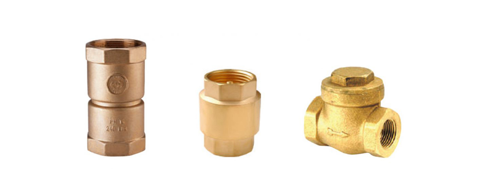
2) Non-return valves: they only allow fluid flow in one direction. Most used are:
– Those with a clapper: when the fluid circulates, it pushes a gate that closes immediately when circulation stops, preventing passage in the opposite direction. They produce little load loss, so they are recommended for primary circuits. It is not advisable to use them in diameters greater than 40 mm.
– The shell: when the fluid circulates, it pushes a spring, which moves the shutter shell, allowing its circulation. When circulation ceases, the howitzer returns to its initial position, preventing passage in the opposite direction.
They cause a greater pressure drop than those with clapet, so they are only recommended for secondary circuits subjected to mains pressure.

Válvula antirretorno: ¿Qué función tiene y dónde colocarla? – STHexpert

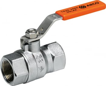
3) Stop valves: they are responsible for totally or partially interrupting the fluid flow through the pipes. Those of total closure separate a part of the installation or isolate it from the service. The partial closing ones produce an additional pressure drop in the circuit to regulate the flow or balance the system.

Instalación solar: Componentes y válvulas para placas solares

4) 3 and 4-way valves: they are used for fluid circulation through alternative routes. They are almost always placed with automatic devices so that an electrical signal, generally coming from a thermostat or probe, activates the mechanism by opening and closing corresponding pathways.

OVENTROP: Válvulas de 3-vías de mezcla y distribución "Tri-CTR" PN16

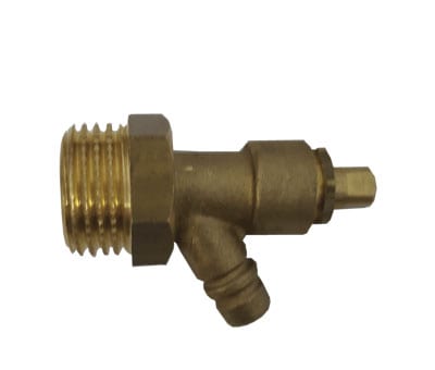
5) Drain valves: they are generally placed in the lower part of the circuits for maintenance operations or replacement of a damaged component of the system.

Válvulas de vaciado archivos - Potermic

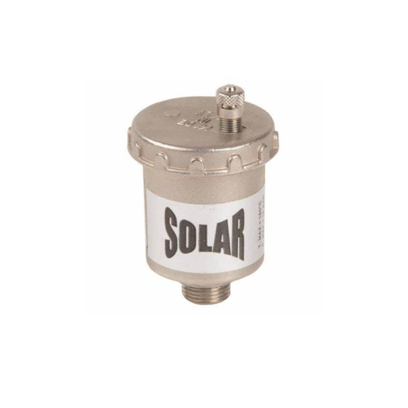
For different reasons (filling, cooling after a large expansion of the heat transfer fluid, etc.) solar thermal systems are sometimes affected by a problem that can impair their operation or greatly reduce their performance: air bubbles in inside the pipes.

To eliminate bubbles from the heat transfer fluid, there are devices called purgers, which are designed to capture these bubbles and expel them to the outside.

Its operation is automatic, due to the fact that the bubbles tend to rise and settle above the fluid, the trap is placed at the highest point of the system.

Sometimes it is mounted on a deaerator, a device that has a great capacity to trap the bubbles in the fluid, the purger being in charge of evacuating the air.

Purgador Solar 3/4" FERCO PS3

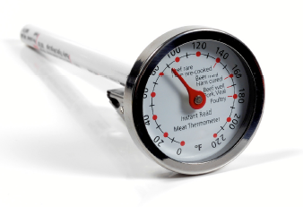
The thermometer will allow us to measure the temperature of the fluid in different places of the system.

The most used are:
Contact: they are placed by holding them on the pipes by means of a clamp.
Immersion: they are inserted inside the pipe, accumulator or exchanger inside a sheath and are provided with a bulb of different lengths. Their reliability is greater because they are in direct contact with fluid.

Termómetro y Termostato - Eficiencia Energética

Thermostats are responsible for transforming a predetermined temperature reading on their scale into an electrical signal that activates a certain mechanism (starts or stops it) depending on the function entrusted to it.

The differential thermostat and the temperature probes that it has must ensure that the circulation pump only works when the collectors can provide a useful gain and stops when there is no capture or it is not sufficient.

One of the probes is placed at the outlet of the collectors and the other at the bottom of the storage tank. The differential thermostat will be connected to the circulation pump. Connections must be made with solder and wires must not have splices.

The mission of the differential thermostat is to compare the temperatures recorded by the probes, so that when there is a predetermined temperature difference between them favorable to the collectors, the circulation pump starts up.

Termostato Varilla Termo Electrico Ø6 x 270 mm. | eBay

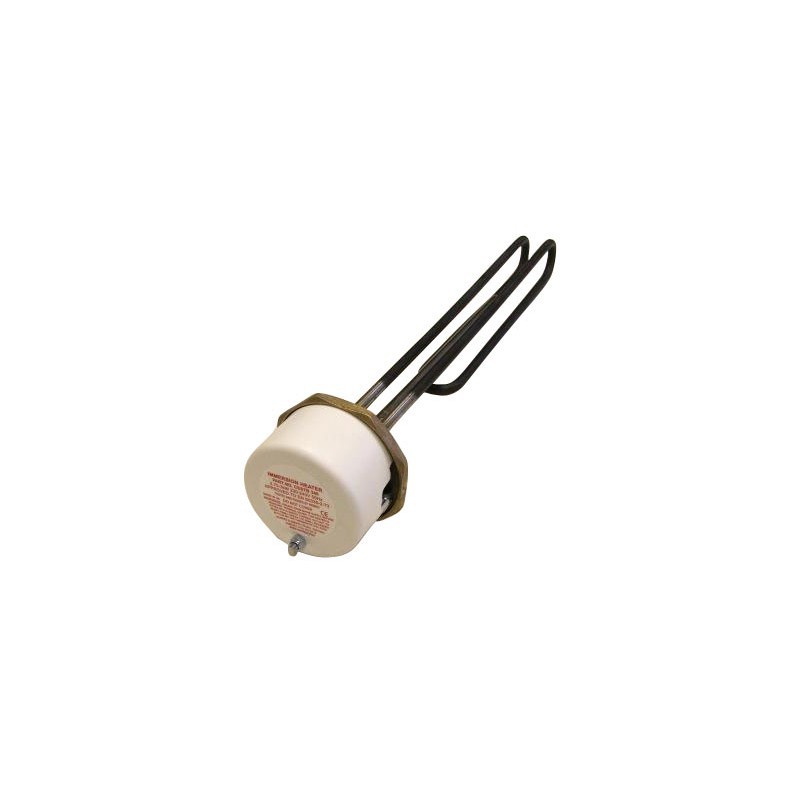
The immersion electrical resistance is an element widely used as an auxiliary system in solar energy systems for the production of DHW. As it is a submerged hot spot in the circuit, it tends to accumulate calcareous deposits. To avoid this, some manufacturers incorporate it in the primary circuit. This is a serious mistake because this energy source can be given priority to the detriment of the energy coming from the collectors.

Resistencia eléctrica 3000w OW-R3

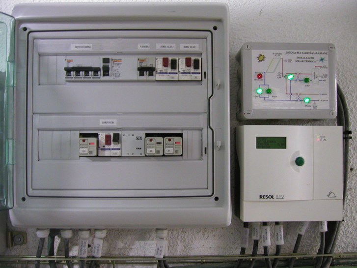
Medium and large systems have an electrical and control device.

The analog variables that must be measured by the monitoring system will be at least 6, and among which the following 4 must be included:

Cold water inlet temperature.
Solar hot water supply temperature.
Temperature of hot water supply to consumption.
Consumption water flow.

With the recorded data, the results will be analyzed and the daily performance of the system will be evaluated. These data will be filed in a historical record of benefits.

Energía Solar Térmica para ACS en un Colegio de Barcelona - ATEGA  Instal·lacions S.L.L. Expertos en Energía Solar

This content was extracted from the Solar Thermal Energy Technical-Commercial Manual and is part of Solar e-learning.

All you need is Sun. All you need is Sopelia.

2021 And The Fable Of Solar Self-Consumption

Previous clarification: we are in favor of renewable energy in general and solar energy in particular. We dedicate ourselves to that.

This does not prevent us from taking a critical look at how the sector is developing.

Making the parallel with a famous rear, on the one hand we have “the resistance” (individuals and companies) and on the other, “the dark side” (public administrations and energy trading companies).

The discourse is that renewable energies, in addition to helping us combat climate change, will provide us with energy independence.

Our territory is full of solar and wind farms and more and more photovoltaic systems are being observed on the roofs.

But the reality is that energy price in some countries has increased almost fivefold in the last 2 years and that solar self-consumption benefits, in most countries and mainly in residential sector, vanish in tolls and unclear compensation systems.

In case of large-scale renewable systems, coupling energy generated with distribution network is still inefficient. To assess its location, in most cases scientific, technical, ecological, economic and social criteria have not been used to minimize its impact on the landscape, biodiversity and the way of life of the inhabitants of the affected territories.

As for solar self-consumption systems, currently they are only interesting in those activities in which solar radiation hours coincide with energy consumption hours.

Making the parallel with another well-known rear, to overcome these obstacles we must find the holy grail as soon as possible: an efficient and cheap energy storage system.

Meanwhile “the dark side” continues to beat “the resistance” by a landslide. One of its members regulates the sector with regulations and procedures for setting rates tailored to the interests of the other, and the other member is a voracious tax collection agent for the former.

We have other bad news … doing things right way is against the interests of “the dark side.”

How should things be done? Relying on 3 basic pillars:

1) Energy efficiency

Making more efficient use of available resources runs counter to the established idea that increasing GDP is synonymous with progress. It would involve manufacturing more energy efficient devices and reducing their planned obsolescence. In short, use fewer resources and generate less waste. Or what is the same, give priority to the environmental quality over the economic quantity.

El momento de la eficiencia energética? | Blog IL3 - UB

2) Renewable energies

Of the 3 pillars, it is the only one in which there is consensus and in which the most progress has been made. The replacement of fossil resources that produce the greenhouse effect with renewable resources for power generation is practically out of question.

Ver las imágenes de origen

3) Distributed generation

Here, too, the clash of interests occurs. Distributed generation is synonymous with energy independence and this does not interest the “dark side”. It would imply less control, fewer tolls, transparent or zero compensation systems, and less tax collection.

Distributed generation entails decentralization in interconnected generation cells and consequently the minimization of losses caused by energy transport. Power generation is close to consumption points, favoring self-consumption. This translates into energy savings, cost reduction and energy system transparency.

Using sites in urban and industrial areas (roofs) close to consumption points would have a lower impact on biodiversity.

The opposite of centralization and control. With a centralized energy network like the current one, energy is generated in plants located at great distances from consumption places. This requires a complex transportation and distribution infrastructure. From an economic point of view it represents a high profitability for its operators, but it entails a high environmental impact and a high performance loss (close to 20%); motivated by the transformation processes necessary to transport electricity.

La ULE dedica un curso a la generación distribuida y fotovoltaica

Is important the contribution of small-scale solar thermal energy with a performance twice that of photovoltaic solar energy.

Many countries, such as Spain, have incorporated it as an essential requirement for obtaining a building license for any new building.

This is very positive, but unfortunately we can affirm that approximately 4 out of 10 of these facilities do not work properly because the inspection is limited to obtaining the building license and not to its operation and subsequent maintenance; as in the case for example of a gas boiler.

Both “the resistance” and “the dark side” know that this is the way.

But the first is scattered and only has the strength to rise from time to time a few ephemeral media characters and the second continues to pull the strings in the shadows with the sole objective of maximizing its benefits.

From time to time they meet to take a photo and issue empty statements of intention of concrete objectives and plans and assign million-dollar budget items that one knows where they will go. The last one was in Rome last October.

From Sopelia we encourage you to join “the resistance” and to continue fighting against climate change, each one in his field and in his day to day because as a friend of ours says: there is no planet B.

All you need is Sun. All you need is Sopelia.

Solar Energy Paraguay

Paraguay has one of the highest proportions of renewable energy in South America. Hydropower constitutes around 99.5% of the installed electricity capacity. This makes it highly dependent on the rivers that feed the country’s main hydroelectric plants, from where most of the electricity produced is exported to neighboring countries.

By 2020, renewable energies had reached an installed capacity of 8,832 megawatts (MW). The hydroelectric capacity represented 8,810 MW (47% of its energy supply). In second place, there is biomass (33%), most of which is unsustainably exploited, and lastly, hydrocarbons (20%), all imported.

Paraguay holds the rare title of the world’s largest exporter of electrical energy, but many argue that it is an inefficient exporter because the compensation it obtains is much lower than the market price of energy; at the same time as an inefficient consumer because it uses a very low amount of its installed hydroelectric capacity.

From the perspective of energy demand, the main energy source is biomass (44%), followed by hydrocarbons (40%) and, in a distant third place, electricity (16%). The main source of energy produced in Paraguay is thus the least used in the country.

Paraguay has ratified the Paris Agreement in 2016, the 2017 National Climate Change Law, and the Nationally Determined Contribution, updated under the Paris Agreement and presented in July 2021.

Qué es la energía solar térmica y para qué sirve?

The Atlas of the solar and wind energy potential of Paraguay is one of the tools developed by Itaipu to make visible data of great relevance for developers of these technologies interested in new generation projects in this country.

That document reflects a promising future for solar technology.

Regarding the solar energy potential, it is represented in average daily solar energy accumulated in one year per surface unit (kWh / m²-year). This map denotes considerable potential throughout the territory, with a positive trend towards the north of the country, registering maximum figures that are between 1850 and 2000 kWh / m²-year, especially between the departments of Alto Paraguay, Boquerón, Concepción, Amambay, San Pedro, Canindeyú and Alto Paraná.

Non-Conventional Renewable Energies such as wind and solar still have very low percentages in the installed energy matrix. For this reason, the Vice Ministry of Mines and Energy of Paraguay (VMME), the Itaipú Binacional, the Itaipú Technological Park (PTI-PY), the National Electricity Administration (ANDE) and other entities, would be drawing up a strategic plan to promote these alternative energies.

Currently, Law 3009 of 2016 is in force. Calls for bids were made within the framework of that law but no awards were made, because at the time projects prices were not better than those of Itaipu.

In addition, they required a self-generation license and sales to third parties were prevented.

With the changes introduced to regulations that regulate the sector, solar is expected to be the most competitive non-conventional renewable technology in 2021.

You could have a solar MW at 39 dollars, while for hydroelectric it would be USD 47 and for wind USD 43.

Diario HOY | ¿Aire, heladeras y otros aparatos movidos a energía solar?: Costos, pros y contras

Every day, thousands of people, mainly in Asunción and the Metropolitan Area, are left without electricity for several hours.

This problem has forced us to consider the need to look for other alternatives that help compensate for the lack of good service and, in turn, face constant power outages.

The use of solar energy, although it is not yet very popular in Paraguay, could be a solution.

All you need is Sun. All you need is Sopelia.

ISOLATED PV SOLAR SYSTEMS DIMENSIONING

Isolated PV systems do not need a connection to an electrical network and their operation is independent or autonomous from said network.

Applications that are currently being implemented the most are small installations for lighting houses that are not reached by the general network, pumping, various agricultural facilities, signaling, hostels, campsites, shelters, summer and weekend chalets.

The criterion followed in isolated PV systems sizing is not so much to produce maximum energy but rather the concept of reliability appears (to ensure the proper functioning of the system, ensuring that failures are minimal).

Sizing an isolated photovoltaic system requires 7 steps:

1. Estimation of electrical load (electrical consumption)

We must know power of each element of consumption and the estimated time of use. Normally the calculation is made using W / h as the unit of energy.

To estimate these values we can consult following link

Ver las imágenes de origen

2. Estimation of solar energy available

Hm is the energy in kWh that affects a square meter of horizontal surface on an average day of month m. From the corresponding table the value is obtained in MJ / m2 (mega joules / m2).

The conversion must be carried out and expressed in Wh / m2 or kWh / m2. Being 1 MJ at 277.77 Wh or 0.277 kWh.

To estimate these values we can consult following link

Ver las imágenes de origen

3. Battery sizing

To define accumulator size, you must set N (Days of autonomy). It is the number of consecutive days that in the absence of Sun, accumulation system is able to meet consumption, without exceeding maximum discharge depth of the battery.

Having identified N and knowing the total energy required Et (final electricity consumption) in a period of 24 hours, we are going to calculate the real energy Er that the modules must contribute to the chosen battery (which will have a maximum admissible discharge depth pd).

The daily energy Er must take into account the different losses that exist:

Er = Et / R

Where R is a global factor of installation performance, whose value will be:

R = 1 – [(1-kb-kc-kv) ka. N / pd] – kb – kc – kv

kb: coefficient of battery performance. It varies between 0.05 (if there are no intense discharges) and 0.1 (for more unfavorable cases).
ka: self-discharge coefficient. If the data does not appear on the battery’s technical sheet, it can be estimated at 0.005 (0.5% daily).
kc: loss coefficient in the converter. If the system does not incorporate an inverter, it is zero. It ranges from 0.2 for sine wave inverters to 0.1 for square wave inverters.
kv: coefficient of other losses. It is usually estimated at 0.15 and 0.05 if we have already considered the performance of each device when calculating consumption.

Once R is calculated and Er obtained, we proceed to determine the useful capacity Cu of the battery. The battery must be able to accumulate the energy to be supplied throughout this period:

Cu = Er. N

To go from Wh to Ah, we will divide Cu by the nominal battery voltage (usually 12 V or 24 V).

Now we calculate the maximum nominal capacity C assigned by the battery manufacturer. These capacities will be assigned for temperatures between 20º and 25º C.

C = Cu / pd

With these data, the batteries offered on the market will be selected that most closely approximates the nominal capacity C obtained.

To estimate these values we can consult following link

Ver las imágenes de origen

4. Dimensioning of modules area

Energy originating in modules that must reach the accumulator (Er) suffers losses originated by the regulator, which are estimated at approximately 10%; therefore the daily amount of energy to be produced by the Ep modules is:

Ep = Er / 0.9

From the following formula we will calculate the HSP (hours of peak sun or hours of sun at an intensity of 1000 W / m2), starting from H expressed in MJ (1 kWh = 3.6 MJ):

HSP = 1 / 3.6k. H (MJ) = 0.2778 k. H

k is the correction factor for modules inclination according to the latitude of installation location.
H is the average daily radiation of each month expressed in MJ / m2.

To access these values we can consult following link

As we have already said, we must base ourselves on the most unfavorable month and also correct according to area climatological factors (clean atmosphere or mountain area = 1.05; area with pollution = 0.95; area with fog = 0, 92).

The ideal orientation is always towards equator and to determine the inclination we can follow recommendations in PV modules support structure post.

To calculate modules number we will use the following formula:

NM = Ep / 0.9. Pp. HSP

Pp is nominal (peak) power of chosen modules. The most suitable modules combination for the installation will be selected (price, available space, load to satisfy, etc.).

It is multiplied by 0.9 to consider possible additional losses that can cause modules dirt, reflection, etc.

If result is not a whole number, it will be rounded to the higher unit if decimal is equal to or greater than 0.5 and lower if it is less than 0.5.

Knowing the total modules number of PV generator and battery nominal voltage, which coincides with installation nominal voltage, it is possible to determine if it is necessary to group the modules in series and in parallel. The number of modules to be connected in series is calculated as follows:

Ns = VBat / Vm

Where:
Ns modules number in series per branch
VBat nominal battery voltage (V)
Vm nominal voltage of the modules (V)

And the number of branches in parallel to connect to supply the necessary power is given by:

Np = NM / Ns

Where Np is the number of modules to be connected in parallel branches.

Ver las imágenes de origen

5. Specify the controller or regulator

For sizing we can consult Solar charge controller post.

The installation will be dimensioned in such a way that the safety factor corresponds to a minimum of 10% between maximum power produced and that of regulator. The minimum possible number of regulators will be used.

To find the number of regulators Nr we will use the following equation:

Nr = Npp. ip / go

Being:
Npp the number of modules in parallel.
ip the peak intensity of the selected module.
go the maximum intensity that the regulator is capable of dissipating.

Ver las imágenes de origen

6. Sizing of the inverter

When sizing the inverter, the power demanded by the load made up of AC devices will be taken into account, so that an inverter will be chosen whose nominal power is slightly higher than the maximum demanded by the load.

For inverter sizing if PV systems has AC devices we can consult Solar converter post.

Ver las imágenes de origen

7. Choice of cable section

To select the cable section, the recommendations in the section Other elements (Wiring) post will be taken into account.

The sizing of the wiring constitutes one of the tasks in which special attention must be paid, since whenever there is consumption there will be losses due to voltage drops in the cables.

We can consult Solar wiring post.

Ver las imágenes de origen

This is an extract of contents included in Technical-Commercial Photovoltaic Solar Energy Manual and Sopelia e-learning training.

All you need is Sun. All you need is Sopelia.

Solar Thermal Insulation

Thermal insulators are essentially characterized by their thermal resistance and thermal inertia.

Thermal resistance is defined as difficulty that a product of a given thickness presents in allowing heat to pass under unit surface conditions, temperature difference and time. By definition, it is ratio of thickness to thermal conductivity.

Thermal inertia is physical ability of a material to maintain its temperature.

The best insulators are air, polyurethane foam, fiberglass, cork (expanded), glass foam, wood fiber sheeting, sponge rubber, PVC, expanded vermiculite, sawdust, loose vermiculite, and linoleum.

Thermal insulation primarily represents economy, because by preventing heta transmission, passage of energy from one body to another is avoided. In addition, thermal insulation represents an investment that will be recovered in a relatively short time, with energy savings that will be obtained, and with best efficiency and operation of equipment and machinery.

If solar thermal system is not thermally insulated there will be a loss of heat and to counteract this phenomenon system will have to resort to auxiliary energy to be able to maintain the required temperature. Therefore, if the system is thermally isolated, heat loss will be avoided and solar energy will be used, preventing auxiliary energy equipment from being activated.

Thermal insulation will also represent protection for personnel who may be in accidental contact with hot surfaces.

Resultado de imagen de aislamiento solar térmico

Characteristics of a good insulator:

1. Low heat conductivity.
2. Lightweight (do not burden system weight)
3. Fireproof and rot resistant
4. That it is not attacked by rodents or insects and that it does not breed insects
5. Inert
6. Easy to place.

Places where insulation is most relevant are: collectors back, pipes and accumulator.

As a reference, minimum insulation thickness of interior pipes is set in Spain by the RITE (Regulation of Thermal Installations of Buildings), as indicated in the following table:

Resultado de imagen de grosor mínimo del aislamiento de las tuberías interiores está fijado en España por el RITE

For materials with a thermal conductivity other than 0.04 W / m ºC, thickness will be determined by multiplying table value by λ and dividing by 0.04.

For pipes sections installed outside, minimum thickness indicated in the previous table must be increased by 10 mm.

The insulating material shall be secured with suitable means, so that it cannot detach from the pipes or fittings.

Insulation will not leave visible areas of pipes or accessories, leaving only the elements that are necessary for proper functioning and operation of components to the outside.

For protection of outdoor insulating material, a plaster cover or coating protected with asphalt paints, fiberglass reinforced polyesters or aluminum sheet may be used. In case of tanks or heat exchangers located outdoors, plastic fabric linings may be used.

Special care must be taken to guarantee pipes insulation durability, especially in outdoor sections exposed to sun, which must have the following insulation characteristics:

• Inalterability due to atmospheric agents and resistance to fungi formation.
• Resistance to solar radiation; otherwise, it must be adequately covered with protective covers or paints.
• Sealing of passages to outside and elimination of thermal bridges.

This content was extracted from the Solar Thermal Energy Technical-Commercial Manual and is part of Solar e-learning.

All you need is Sun. All you need is Sopelia.

Panama Solar PV

Commitments that Panama acquired in the Paris Agreements are contained in what is known as the National Determined Contributions.

These are ethical commitments, not mandatory, that do not imply sanctions for non-compliance.

The commitments of the Republic of Panama in this regard are to generate 30% of electricity by 2050 with new renewable sources (solar and wind).

It is important to differentiate between installed power and effective generation.

In 2017, while solar and wind capacity reached almost 12%, their generation represented only 6%.

Currently Panama has an installed capacity of 270 MW of wind, 194 MW of solar parks, and 35 MW of solar in autoconsumption condition.

Penetration of solar energy remains low. Towards the end of 2019 it only represented 2% of total generation matrix.

In the first quarter of 2020, the total generation was 2,842,636 kWh; 256,638 kWh of them came from wind, that is, 9%, while 91,293 kWh from photovoltaic means 3.2%.

If to this is added the 1,181,553 kWh accounted for by hydro (41.5%), it is obtained that energies not based on fossil fuels represented 53.7% during the first quarter of 2020.

Compared to the same period of 2019, total renewables increased their generation by 18%.

With an investment of about 160 million dollars, the 150 MW Penonomé Photovoltaic Solar Plant is considered the largest solar installation in Central America.

Panama will be a pioneer in the implementation of a modern solar energy system called “Maverick”.

It is a revolutionary pre-built and pre-wired solar solution that folds up, ships to site, and then deploys. It is one of the easiest and fastest ways to add solar resources, using fewer tracts of land.

Panama will be one of the first countries where this technology will be implemented in a 2 MW fast track project.

The innovative solution enables customers to install solar projects at a rate three times faster, while supplying up to two times more energy using the same terrain as traditional solar installations.

The pre-manufactured modules are deployed from a moving vehicle that places them in a certain area.

5B plans module pre-fab facility in Adelaide, "gigafactory" in Asia | RenewEconomy

Large local companies have shown a growing interest in the use of solar energy for their electricity supply given the change in mentality of Panamanians who are showing concern about climate change and from there they have already achieved the signing of several agreements of power sales (PPAs) with large long-term clients for at least 22 years.

As in most countries, it is committed to centralization and large-scale projects and not to empower users and democratize energy.

The role of the prosumer should be promoted and distributed generation policies developed.

The Office for Latin America and the Caribbean of the UN Program for the Environment (UNEP) together with the Spanish Agency for International Development Cooperation (AECID) launched the Generación SOLE initiative, which seeks to promote innovative financing models for deployment of photovoltaic solar generation distributed in the region with immediate actions in Panama.

The Generación SOLE initiative seeks to strengthen the capacities of commercial banks to create financing options aimed at the final consumer, whether residential, commercial or industrial. The initiative aims to promote disruptive growth in the solar generation market.

All you need is Sun. All you need is Sopelia.

On-Grid Systems Dimensioning

There are two modes of on-grid connection:

– User continues to buy the electricity they consume from distributor at the established price and also owns an electricity generating system that can bill the kWh produced at a higher price.

– In Self-consumption or “Net Metering” the system will be able to inject energy into the network when its production exceeds self-consumption, and extract energy from it otherwise.

A 1.5 kWp system occupies about 22 m2 of roof (12 m2 of modules net surface) and will feed as much energy to the grid as that consumed by a small house throughout the year.

COMO CONECTAR PANELES SOLARES A SU PROYECTO SOLAR

Estimation of energy produced by an on-grid PV system we will carry out is a simple prediction that consists of mere multiplication of an irradiation value by another of peak power that usually leads to estimates that are far from system real behavior.

An approach to more exact calculations should consider different factors that influence the useful energy generation process (PV generator location, temperature variations, shadows, maximum available power, second-order phenomena, inverter characteristics, etc.).

Whatever procedure adopted, we should try to combine simplicity with precision.

When calculating an on-grid PV system, following conditions must be taken into account:

1- System nominal power (kWp)

In practice, it will be established based on available surface area, investment to be made and amount of solar electricity to be generated.

Once module power to be used is determined, Wm, we multiply it by modules number to be installed Nm to obtain system peak nominal power Pmp:

Wm. Nm = Pmp

2- Electric energy to generate

The energy that could be obtained for each month can be calculated using the following expression:

Em = km. Hm. Pmp. PR. nm / GCEM

Where:

Em is solar energy production of month m in kWh.

km is correction factor to be applied due to modules inclination for month m (its values for northern hemisphere can be accessed in Censolar tables and at http://www.cleanergysolar.com/2011/09/15/tutorial-tables-correction-factor-of-k/) according to latitude of system location.

Hm is energy in kWh that affects a square meter of horizontal surface on an average day of month m. From the corresponding table the value in MJ / m2 (mega joules / m2) is obtained. The conversion must be carried out and expressed in kWh / m2.

To obtain the average daily radiation of each month expressed in MJ / m2 anywhere in the world, we can consult Opensolar DB.

The monthly mean daily irradiation can also be obtained from renowned databases such as NASA http://eosweb.larc.nasa.gov/sse or Joint Research Center [JRC], http://sunbird.jrc.it/pvgis /pv/imaps/imaps.htm Institute for Environment and Sustainable Renewable Energies, Ispra (Italy).

To convert from MJ to Wh or kWh we use the following equivalence:

1 MJ = 106 J = 0.277 kWh = 277.77 Wh

Pmp is the peak power of the generating field expressed in Kwp.

PR is the system energy performance factor or performance ratio defined as system efficiency in real working conditions. In practice, PR = 0.8 is usually taken

nm is number of days in month considered.

GCEM = 1kW / m2 CEM means Standard Measurement Conditions universally used to characterize solar generators, which as we have already seen are equivalent to: Solar irradiance: 1000 W / m2; Spectral distribution: AM 1.5 G; Cell temperature: 25 ° C.

Sistema solar fuera de la red o conectado? Diferencias, ventajas y desventajas

Estimate of the energy injected annually into network will be obtained by adding the energy values Em for each of the twelve months of the year.

The key element in a grid-connected system is the inverter, which ensures that the circuit-module-grid coupling is perfect, safe and efficient.

This content was extracted from the Commercial Technical Manual of Photovoltaic Solar Energy and is part of Sopelia Solar e-learning.

All you need is Sun. All you need is Sopelia.

Solar Thermal Pumping Systems

There are three main types of pumping systems or electrocirculators:

1. Alternatives
2. Rotary
3. Centrifuges

Usually used in solar thermal energy systems are centrifuges.

The electrocirculator or pump is the element of solar thermal system in charge of moving the fluid from primary circuit, or other closed circuits of the system (circuit between accumulator and external exchanger, recirculation rings for domestic hot water, heating circuits, etc.).

In the particular case of primary solar circuit, the objective of forcing this circulation is to transport the heat from solar collectors to exchanger, compensating for pressure losses (resistance to fluid movement) of different accessories that make up the circuit: pipes, valves, branches, manifolds and exchanger.

In most solar hot water production systems, circulating flows are not very important. The most widely used pumps are in-line, single-phase and small-power type.

Ver las imágenes de origen

Different materials are used to manufacture pump body depending on the circuit in which it is integrated:

Closed circuits: cast iron is the most used material in manufacture of the hydraulic body of pumps intended for these circuits, since it is cheaper than other materials. Circulating liquid is always the same, generally water with anti-calcareous and antifreeze additives. In addition, this fluid is not for consumption, so it does not have to keep the characteristics of water unchanged.

Open circuits: bronze and stainless steel are the most widely used materials in open circuits. The liquid that circulates is drinking water and, therefore, salts that it contains dissolved cause calcification and corrosion problems in certain materials, such as cast iron. Furthermore, having to be in contact with drinking water, the construction material of roller must keep the characteristics of water unchanged.

The behavior of the electrocirculator is represented:

P = C. p

Where:

P is the required power

C is the flow (l / sec) between two points of a pipe with pressure difference p

This means that pump power is a function of head loss and flow rate.

With these two axes manufacturer will represent it in its characteristic curve, each pump having its own characteristic curve.

Ver las imágenes de origen

With time passage, pipes acquire corrosion, so pressure drop increases. Generally the calculations are made as if there were only water in the system, while antifreeze is often added, for this reason in practice the chosen pump must be a little oversized.

The pumps usually have several speeds and manufacturer indicates this in their graphics. It is advisable to work at an intermediate speed in order to increase or decrease speed if we have fallen short or have oversized the pump respectively.

By associating two electric pumps in series, manometric height is greatly increased and flow rate is low, while if they are connected in parallel, flow rate increases greatly and pressure does little.

Pump has to counteract pressure drop only on the worst track. If circuit is balanced, one will be chosen at random.

Circuit is preceded by a filter to prevent impurities from entering the welds and rest of system into the pump. It also has a non-return valve to prevent backflow of heat transfer fluid from collector to the pump. The cutoff wrenches are used in case of pump failure to be replaced or repaired.

By operating stopcocks, we obtain delivery pressure and suction pressure on the manometer. If we subtract the results, pressure drop is obtained, which must coincide with that of the system.

At the rear electrocirculator must have a small pressure to be able to start, regulations indicate that it must be at least 2 bar or 5 bar for high temperatures.

Funcionamiento de la energía solar térmica | Ekidom S.L. Energías ...

Experience indicates that for a flat collectors system minimum necessary flow is 50 liters per hour per m2 of collecting surface if heat transfer fluid is water. If it is an antifreeze mixture, flow rate will be higher to compensate for lower capacity to transport heat. For this we must take into account relationship between antifreeze mixture Ce and water Ce.

In general, thermal flow should be at least equal to 50 kilocalories for each collector´s square meter, for each hour and for each thermal jump degree centigrade. For example: if fluid experiences a thermal jump of 5º C in collectors, minimum thermal flow will be = 50 x 5 = 250 kcal / h / m2.

When we speak of a certain flow we are referring to volume that each collector’s square meter actually passes through in time unit considered.

Once the flow has been found, head losses that this flow causes in system must be calculated, which will be the sum of head losses of each components (pipes, accessories, exchanger, etc.).

The best way to carry out calculation will always be to go to the flow-pressure characteristic curves in pump´s technical data sheet.

This content was extracted from the Solar Thermal Energy Technical-Commercial Manual and is part of Solar e-learning.

All you need is Sun. All you need is Sopelia.

Panama Solar Thermal

Despite solar radiation high levels and its strong dependence on fossil fuels, only in 2018 did Panama begin to promote solar thermal technology incorporation.

The starting point was “Termosolar Panamá”.

This is a project executed through an inter-institutional alliance between the UN Environment Regional Office for Latin America and the Caribbean and the National Energy Secretariat (SNE), with the financial support of the Global Environment Facility (GEF) and the support of various allies from public and private sectors.

The objective is to install 1 million square meters of solar thermal technology applications for water heating throughout the country by 2050. With this, country will reduce 6.4 million tons of CO2 and Panamanians will save more than US $ 3 million annually in fossil fuels.

Some 10 million dollars will be invested to achieve this objective.

Termosolar - Calentamiento de agua con energía solar en Panamá ...

The project began in June 2018 and has been supported by a broad portfolio of partners from public and private sectors, such as the Banco General, the Panama Green Building Council, the Technological University of Panama, the Municipality of Panama, the National Institute of Vocational Training and Training for Human Development (Inadeh), among others.

One of the 4 direct objectives of the project is the implementation of demonstration pilot projects with solar water heating systems nationwide. This involved carrying out energy audits in residences, shops and hospitals that were selected to participate; which led to the identification of savings opportunities and market potential that exists in the country.

The project has so far installed a total of 100 pilot heaters in health and social care buildings, hotels, private companies and private residences.

Some of the centers where the use of technology was contemplated are the San Miguel Arcángel Hospital in Panama, the Luis “Chicho” Fábrega Hospital in the province of Veraguas, the José Domingo de Obaldía Maternal and Child Hospital in the Chiriquí province, and children dining rooms in Panama City.

The Veterinary Wildlife Clinic of Panama Summit Municipal Park became first beneficiary of public sector.

Of 100 pilots established, 30 were assigned to residential sector.

Panamá instalará 100 calentadores solares en edificios públicos y ...

The project envisages the development of a package of political and fiscal measures that allow the growth of solar thermal technology in country, as well as the adoption of quality assurance and control standards, both for equipment to be imported or manufactured, and for techniques of equipment installation.

Termosolar Panamá also contemplates the creation of capacities and professionals training for solar water heating systems management.

The General Bank designed a financial mechanism to grant credit lines to residential and commercial sector that it wishes to implement this system. Feasibility analyzes and design of solar water heater system will be financed by the project.

This government initiative has managed to stimulate the reactions of Panamanian private company. Scopes with an interesting and very marked potential are hotel, food and health sectors.

All you need is Sun. All you need is Sopelia.

PV Systems

Coupling of two or more modules in series produces a voltage equal to the sum of individual voltages of each module, keeping the intensity unchanged.

In parallel connection, it is the current that increases while voltage remains the same.

The most common is to select modules of desired voltage (those of 12 V are the most used) and combine them in parallel so that the total intensity (and therefore resulting power) is necessary to satisfy the electrical demand.

Interconnecting modules must have the same i-V curve to avoid decompensation.

If in a group of modules connected in series one of them fails (due to failure or shade), this module becomes a resistive load that will hinder or prevent the passage of the current generated by the other modules in the series. The module in question could be totally damaged.

To prevent this situation, modules connected in series are equipped with a by-pass or bypass diode, connected in parallel between their terminals. This element provides an alternative path to current generated by the other modules in the series.

There are different types of configurations that respond to systems characteristics and especially to load type. Most common ones are detailed below:

• Modules directly connected to a load
It is the simplest system. Photovoltaic generator connects directly to the load, normally a direct current motor. It is used for example in pumping water. In absence of batteries or electronic components, reliability increases but it is difficult to maintain efficient performance throughout the day.

Ver las imágenes de origen

• Modules and battery
This setting can be used to replenish self-discharge of a battery or in small power rural electrification systems. One or two modules connected in parallel are usually used to achieve the desired power.

Ver las imágenes de origen

• Modules, battery and regulator
In this configuration, photovoltaic generator is connected to a battery through a regulator so that it is not overcharged or reaches an undesired depth of discharge. Batteries supply loads in direct current.

Ver las imágenes de origen

• Modules, battery, regulator and inverter
When AC power is required, an inverter will be incorporated into the scheme of previous configuration. Power generated in the photovoltaic system can be completely transformed into AC or DC and AC loads can be simultaneously supplied.

Ver las imágenes de origen

• Network connected systems
Grid-connected photovoltaic systems are made up of a photovoltaic generator that is connected to the conventional electrical grid through an inverter.

Ver las imágenes de origen

There may be two cases:

– The system injects energy into the network when its production exceeds self-consumption, and extracts energy from it otherwise.
– The system only injects energy into the network.

Fundamental difference between an isolated photovoltaic system and those connected to the grid consists in the absence, in the latter, of the battery and charge regulation.

The inverter, in grid-connected systems, must be in phase with the grid voltage.

Here are some examples of photovoltaic systems:
– Centrals connected to network with subsidy production.
– Microwave and radio repeater stations.
– Villages electrification in remote areas (rural electrification).
– Medical facilities in rural areas.
– Electric current for country houses.
– Emergency communication systems.
– Environmental data and water quality surveillance systems.
– Lighthouses, buoys and maritime navigation beacons.
– Pumping for irrigation systems, drinking water in rural areas and watering holes for livestock.
– Beaconing for aeronautical protection.
– Cathodic protection systems.
– Desalination systems.
– Recreational vehicles.
– Railway signaling.
– Systems for charging ship accumulators.
– Power for spaceships.
– SOS posts (road emergency telephones).
– Parking meters.
– Recharge of scooters and electric vehicles.

This content was extracted from the Commercial Technical Manual of Photovoltaic Solar Energy and is part of Sopelia Solar e-learning.

All you need is Sun. All you need is Sopelia.