Tag Archives: solar energy in latin america

Solar Tracking Systems

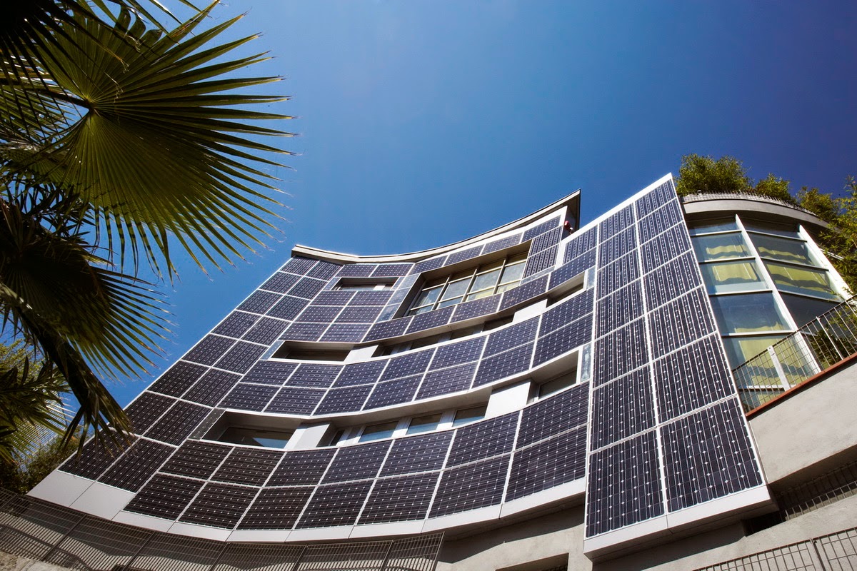
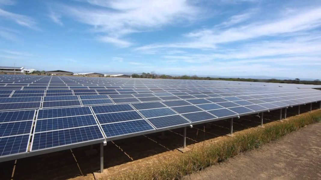
To harness as much solar energy as possible, collection surface must always be perpendicular to the sun’s rays and this can only be achieved if modules are equipped with a solar tracking mechanism.
Using these mechanisms, total energy received in a day can be up to 35% higher compared to that received by a static module.

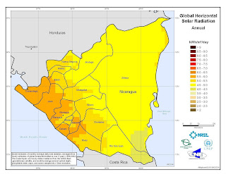
This difference in performance is reduced in cases of frequent cloudy days and in all those weather conditions in which the relationship between energy received by direct radiation and that received by diffuse radiation tends to decrease. That is why it is only recommended to use it in areas of low cloudiness.

A detailed analysis must be carried out to verify that performance increase achieved more than compensates for energy consumption and the cost and maintenance of monitoring mechanisms.

The two types of movement are:

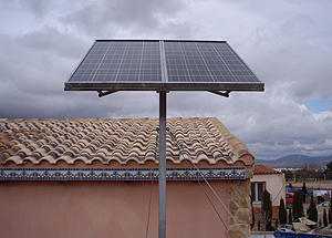
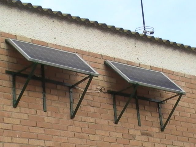
1. Single axis: only allows rotation around a horizontal, vertical or inclined axis. You can track sun azimuth or height, but not both at the same time.

Ver las imágenes de origen

2. 2-axis: in addition to the east-west rotation movement, a second rotary movement on a horizontal axis is also possible by varying the module angle with respect to the horizontal plane. They can be monopost (a single central support) or carrousel (several supports distributed along a circular surface).

Ver las imágenes de origen

We can find different solar tracking systems. The most common are:

1. Passive tracking systems: These devices do not use electricity or have a motor. There are two North American patents. The first (Robbins Engineering) is based on Freon gas pressure expansion and contraction contained in two cylinders located on each side of the structure. The second (Zomeworks) is a gravity system based on the variation of the weight of a fluid contained in a container that when evaporated passes to another.

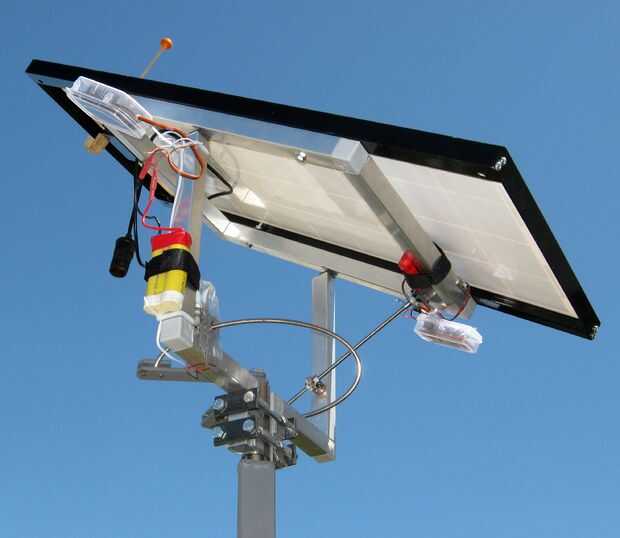
2. Tracking by sensors: the sensor is the element that allows the detection and measurement of the lack of direction between the sun vector and the normal to capture surface. The sensor is usually made up of pairs of photosensitive elements mounted on the module and moving in solidarity with it.
The photosensors use direct solar radiation to detect sun position. Tracking impossibility when sun occultations occur and need to spend time recovering address when sun reappears are inherent characteristics of all systems of tracking based on photosensors.
Deviation detected by the photosensors transmits an actuation signal that controls motors operation to achieve module movement. Constant speed motors are often used that operate intermittently so that the addressing error is kept within a tolerance band.
Systems using photosensors are used for small and medium systems.
Between one day’s sunset and the next day’s sunrise, the module must be placed in the sunrise position because once the sun has risen, much time would be lost in the 180º turn necessary to regain direction. For this, a clock is used that generates the appropriate order.

3. Tracking by calculated coordinates: this system follows sun position by calculating its astronomical coordinates and does not require solar rays physical presence. This circumstance renders coordinate systems immune to cloudy days and other circumstances that can produce addressing errors in a photosensor, as happens for example with flashes.
The use of computer controlled systems has the additional advantage that certain changes can be made at software level only.
It can also include additional functions such as bringing the modules to a position of maximum security against inclement weather or the return at night.

Sopelia has developed Solar Layout, the Android App that allows to obtain the inclination, orientation and distance between rows of photovoltaic modules at the installation site.

This content was extracted from the Commercial Technical Manual of Photovoltaic Solar Energy and is part of Sopelia Solar e-learning.

All you need is Sun. All you need is Sopelia.

Nicaragua Solar Thermal

Undoubtedly, the emblematic project, in terms of thermal solar energy, is the system inaugurated on October 9, 2018 at the Doctor Alejandro Dávila Bolaños Military Hospital in Managua.

With an investment of US $ 4.3 million financed through a soft loan from Oesterreichische Kontrollbank and Raiffeisen Bank International and with the United Nations Agency for Industrial Development (UNIDO), and the National Production Center more Clean from Nicaragua support; This system provides 30% of the demand required for air conditioning and 100% of the demand for hot water (used in various hospital operational functions, such as: personal, patients and doctors hygiene, food cleaning and preparation in the kitchen, for laundry area, among others).

The solar system was installed in a 4,450 square meters area, is composed of 338 thermal solar panels and will have an environment positive impact eliminating more than 1,100 tons of dioxide carbon emission each year.

It is the second largest system in the world, the largest in hospitals and unique in Latin America.

Resultado de imagen de energía solar hospital militar nicaragua

Despite the increase in systems number, solar energy only represents 1% of Nicaragua’s energy matrix.

There is a feeling that decision making is more market focused and not as a development issue.

The key is to associate the solar technology development with economic activities, establish a relationship between water resources, renewable energy and food security and base on renewable energy the climate change adaptation.

Currently solar energy provides energy security in contrast, for example, to energy supply via hydroelectric dams that depends on rains that are varying more and more throughout the region due to climate change.

Resultado de imagen de energía solar térmica nicaragua

Energy sources diversification becomes indispensable and has led to a solar energy investments growth.

This has been possible due to public resources contribution to support this technology development, the political commitment and the role carried out by the private initiative.

In this sense, it is worth highlighting the work that the BID is doing in the region.

In spite of advances, the pending subject continues being the regional energetic integration.

An energy networks extension at regional level would help lower costs and a energy supply diversification would guarantee greater energy security.

All you need is Sun. All you need is Sopelia.

Architectural Solar Integration

Photovoltaic solar energy is the one that best integrates into the urban environment. For this reason, architectural solutions that incorporate it have emerged. Some are listed below.

In homes with a tiled roof, these can easily be replaced by same type photovoltaic tiles, since it is not necessary to change canning or slats and roof structure remains the same.

Ver las imágenes de origen

Aluminum facades integrating photovoltaic cells are an alternative for new buildings or renovation projects.

Ver las imágenes de origen

Photovoltaic modules with transparency together with aluminum profiles can be easily integrated into vertical walls, ceilings and roofs. These transparent modules are available in a wide range of applications, shapes and opacity.

Photovoltaic cells are embedded in the laminated safety glass. By varying glass weft position and density, it is possible to adjust light transmission and shadow effect inside the building.

For opaque solar modules in walls it is necessary to incorporate insulating materials that are behind to provide the necessary thermal barrier. The opaque and transparent modules can be combined on the same facade, improving building energy, thermal and acoustic efficiency.

Ver las imágenes de origen

In addition to producing clean electricity, ventilated photovoltaic facade system incorporates benefits in building thermal and acoustic insulation. The thermal envelope can cause savings of between 25-40% of the energy consumed in the building.

Ver las imágenes de origen

A photovoltaic skylight, in addition to photovoltaic generation, provides bioclimatic properties of thermal comfort inside the building due to the insulating glass air chamber. It also facilitates natural lighting and prevents UV rays and infrared radiation from penetrating into the building (improving comfort and avoiding premature materials aging).

Ver las imágenes de origen

A photovoltaic canopy constitutes a constructive solution that combines electrical energy generation with solar protection properties and against adverse weather conditions.

The orientation, the minimum slope, the dimensions or the wind and snow loads are important factors to take into account when designing the structure.

Ver las imágenes de origen

A photovoltaic car park consists of a structure that, in addition to protecting the vehicle, guarantees the in-situ energy generation for its grid discharge, self-consumption or electric car batteries supply.

Ver las imágenes de origen

The first photovoltaic ceramic floor has also been released. It consists of photovoltaic solar glass integrated in high ceramic pavements, these being fully passable. It can be integrated into any project and environment without this giving up the design or aesthetics of it.

Ver las imágenes de origen

Buildings, by integrating photovoltaic modules, create a world of possibilities. The great variety, shapes, colors and structures of photovoltaic cells, glass and profiles allow a modern architectural approach and also an innovative design combining elegance and functionality.

Sopelia has developed Solar Layout, the Android App that allows to obtain the inclination, orientation and distance between rows of photovoltaic modules at the installation site.

This content was extracted from the Commercial Technical Manual of Photovoltaic Solar Energy and is part of Sopelia Solar e-learning.

All you need is Sun. All you need is Sopelia.

Solar Thermal Pipes

Connection of different components of the solar system is carried out with pipes, until the necessary hydraulic circuits are formed.

Normally, materials used for primary circuit pipes are copper, black steel and plastic materials

The cross-linked polyethylene pipes can be used without problems, provided that manufacturer guarantees their use above 120º C.

Galvanized steel should not be used in primary circuits (from collectors to storage) due to the strong deterioration that zinc protection undergoes with temperatures above 65º C.

In general, the fluid velocity must not exceed 1.5 or 2 m / s in the primary circuit.

Pipes diameter can be selected so that fluid flow velocity is less than 2 m / s when pipe runs through inhabited places and at 3 m / s when the route is outside or by uninhabited places.

When steel is used in pipes or fittings, working fluid pH should be between 5 and 9.

Pipes dimensioning will be carried out in such a way that the load unit loss in pipes never exceeds 40 mm of water column per linear meter.

The circuit load total loss must not exceed 7 m of water column.

The maximum load loss is applicable to primary circuit and secondary circuit. If it were larger, we would be obliged to choose the immediately superior pipe diameter.

For pools heating, PVC pipes are used, which can have large diameters without a significant additional cost.

All piping networks must be designed in such a way that they can be emptied partially and totally, through an element that has a minimum nominal diameter of 20 mm.

Ver las imágenes de origen

For pipeline selection, following aspects must be taken into account:

1º Fluid compatibility:

Materials to be used for ACS circuits may be:

• Metallic:

– Galvanized steel, UNE-EN 10.255 M series (only in cold water).
– Stainless steel, UNE-EN 10.312, series 1 and 2.
– Copper, UNE-EN 1.057.

• Thermoplastics:

– Non-plasticized polyvinyl chloride (PVC), UNE-EN 1.452.
– Chlorinated polyvinyl chloride (PVC-C), UNEEN ISO 15,877.
– Polyethylene (PE), UNE-EN 12.201.
– Crosslinked polyethylene (PE-X), UNE-EN ISO 15.875.
– Polybutylene (PB), UNE-EN ISO 15.876.
– Polypropylene (PP) UNE-EN ISO 15.874.
– Multilayer polymer / aluminum / polyethylene (PE-RT), UNE 53.960 EX.
– Multilayer polymer / aluminum / polyethylene (PE-X), UNE 53.961 EX.

Aluminum tubes and those whose composition contains lead are expressly prohibited.

2º Work pressure:

A minimum pressure of 1 bar and a maximum of 5 bar must be guaranteed at all points of consumption; so you can take 5 bars as pressure for series selection.

Although tanks safety valves are usually set at 8 bar this is a more appropriate design pressure.

3º Working temperature:

Hot water and heating pipes should remain stable with system working temperatures, sporadically be able to reach temperatures close to 95 ° C and continue to resist with a life expectancy of at least 50 years.

4º Charge loss:

When a liquid circulates inside a straight tube, its pressure decreases linearly along its length, even though it is horizontal.

That pressure drop is called charge loss.

Valves, constrictions, elbows, direction changes, derivations, etc. they cause load local or singular losses that must also be taken into account.

Total load loss, which is the sum of linear load loss and singular load losses, must be determined.

Ver las imágenes de origen

5º Pipe size:

To calculate pipe size we start from the flow data.

We must determine pipeline minimum diameter (ie the most economical) without load loss exceeding a reasonable limit, so as not to be forced to use a higher power pumping group with the consequent energy waste.

We know from experience that fluid circulation speed maximum recommended is approximately 1.5 m / s if it does so continuously (primary circuits) and 2.5 m / s if it does so at intervals (secondary consumption circuits).

It is also recommended (or required) that pressure drop for each tube linear meter does not exceed 40 mm ca.

These 2 conditions impose a lower limit on pipe diameter.

It is usual to start from an estimated diameter based on experience in similar systems and verify that choice implies values of load loss and speed lower than recommended maximums.

If this is not the case, verification should be repeated for an immediately larger diameter.

If on contrary, we can select a smaller diameter than initial one, we will save on material; especially if circuit has a considerable length.

As a first approximation, we can resort to following formula:

D = j C 0.35

Being:
D diameter in cm
C flow in m3 / h
j 2,2 for metal pipes and 2,4 for plastic pipes.

Initial estimation, whatever method used, must be verified by using load loss tables or abacuses.

There are tables and specific abacuses for each type of material (copper, steel, plastics) that allow to determine load loss due to friction and fluid speed in the tubes.

This content was extracted from the Solar Thermal Energy Technical-Commercial Manual and is part of Solar e-learning.

All you need is Sun. All you need is Sopelia.

Solar Nicaragua

Nicaragua claims to be less dependent on thermal energy, which is produced based on petroleum derivatives, and therefore executes solar development projects on the Caribbean coast and in country rural areas.

One of the first initiatives back in 2009 was the Euro Solar program, which benefited 42 communities (7,000 families) in the North Atlantic Autonomous Region (RAAN), generating electricity for health services, education and Internet and telephony communication in community centers.

Then Nicaragua depended 80% of energy generated from petroleum derivatives.

Due to its location, Nicaragua is a country with high potential for solar energy use and at same time has one of the lowest electrification rates in the region.

In 2015, with the objective of bringing electricity to North Atlantic Autonomous Region communities and interior municipalities, the Mulukukú Electric Substation was built, which included 200 kms of transmission lines construction between Siuna and Puerto Cabezas (RAAN), where 1,500 solar modules and several electrical substations were installed.

Nicaragua’s largest photovoltaic park, Astro Solar Plant, was installed, which with 3 MW in the Tipitapa municipality supplies electricity to the Zona Franca Astro industrial park.

Ver las imágenes de origen

Energy generation from renewable sources development had important fiscal benefits thanks to Law 901:

Payment exemption of Import Tariffs (DAI) and Value Added Tax (VAT), on machinery, equipment, materials and supplies used for pre-investment and construction work, including the construction of subtransmission lines necessary to energy transport from generation plant to National Interconnected System (SIN).

Payment exemption of Income Tax (IR) for a period of 7 years from project entry into commercial operation.

Payment exemption of Municipal Taxes on real estate, sales and registration for a period of 10 years from project entry into commercial operation.

Resultado de imagen de energía solar nicaragua

Renewable energy in Nicaragua continues to advance smoothly. In 2006, renewable energy represented only 25% of national energy matrix, mainly hydroelectric and geothermal. Until December 2018, renewable energies accounted for 59% of national energy matrix, although in some moments of last year it reached up to 80% of total generation.

Regarding renewable generation contribution by sector, it is estimated that biomass with sugar cane residues contributed 216 MW; hydroelectric energy 150 MW; geothermal 154 MW; wind energy 186 MW; and solar 13 MW. Geothermal energy has been considered the energy of the future of Nicaragua because compared to wind and hydroelectric, it is more firm and constant in its level of generation and has great potential.

Despite these advances, Nicaragua continues to be the country with the most expensive Central American energy in industrial sector. Only those who consume less than 150 kWh per month pay for cheap energy, which mainly benefits the residential consumer.

The origin of these high prices is in the need and urgency of government income, which are obtained in national energy tariff and used to pay internal and external debts.

The main obstacles to distributed solar generation development in Nicaragua are the high initial investment represented by a system for most Nicaraguans and the lack of a law that promotes and regulates electricity sale from small photovoltaic systems connected to the grid.

It is necessary to amend Law 532 or adopt a new law that establishes a reasonable sales rate, incentives for producers, network operators and consumers, as well as simplifying bidding processes in the contracting of energy for small residential systems and the industrial and services sectors.

Number of renewable energy professionals increases every year. New generations are more aware of environment damage that has been done and of solar energy potential. This new Nicaraguan generation must work to reduce energy prices and take advantage of solar energy to provide Nicaragua with a more sustainable and just future.

All you need is Sun. All you need is Sopelia.

PV Modules Support Structure

Regarding situation of photovoltaic modules, there are the following general possibilities:

Flooring: It is the most usual way of installing modules groups (especially in solar farms) and has great advantages in terms of wind resistance, accessibility and ease assembly.
However, it is more susceptible to being buried by snow, flooding or being broken by animals or people.

Ver las imágenes de origen

Pole: very used in small dimension systems, if it has a mast. It is the typical assembly type of isolated communication equipment or lampposts feeding.

Ver las imágenes de origen

Wall: good anchor points must be available on a built building. Accessibility can present some problems.

Ver las imágenes de origen

Roof: one of the most common because generally enough space is available. It also presents problems of snow cover and risks in roof fasteners waterproofing.

Ver las imágenes de origen

If system is located in an urban area, most common is to place the module on the roof.

In structure assembly, roof sealing must be ensured by waterproofing elements use.

A study must also be carried out to determine if ceiling will support modules and support structure weight.

However, main factor when fixing the structure is wind strength. Structure must withstand winds of at least 150 km / h.

On terraces or floors, the structure should allow a minimum height of the module of about 30 cm. In mountain areas or where there is abundant snowfall, it must be higher.

The structure and supports should preferably be anodized aluminum, stainless steel or galvanized iron and stainless steel fasteners.

Anodized aluminum is lightweight and highly resistant.

Stainless steel is suitable for very corrosive environments and has a longer useful life but its cost is high.

Galvanized iron structures offer good protection against external corrosive agents with the advantage that zinc is chemically compatible with lime and cement mortar, once these are dry.

Structures come in kits or standard profiles that are on the market and a specific system structure can be built.

Supports designed for a specific solar module are usually cheaper than those manufactured in order to be able to hold any type of module. However, it will surely be the latter that will end up developing in greater numbers in near future.

Normally, a solar modules support has the following characteristics: it has a plate provided on its upper face with quick coupling means for modules and one or more holes for the screws to be introduced and thus join the plate to the support. The support also has fastening means attached to plate lower face for fastening to lower structure.

Orientation will always be towards the equator and the following inclinations are recommended:

Systems with priority function in winter (eg: mountain lodge): 20º higher than place latitude.

Systems with uniform operation throughout the year (p.e .: home electrification): 15º greater than place latitude.

Systems with priority operation in spring and summer (p.e .: campings): same as place latitude.

Systems whose objective is to produce the greatest amount of energy throughout the year (eg: connection to the grid): 85% of place latitude.

The reason for inclination increasing, compared to that recommended for solar thermal collectors, is that generally in the case of photovoltaic systems there is no auxiliary energy system and it is necessary to capture all the energy possible in the most unfavorable period (winter).

Sopelia has developed Solar Layout, the Android App that allows you to obtain the inclination, orientation and distance between rows of photovoltaic modules at the installation site.

This content was extracted from the Solar Photovoltaic Energy Technical-Commercial Manual and is part of Solar e-learning.

All you need is Sun. All you need is Sopelia.

Solar Thermal System Protection

The correct design of a solar thermal system involves foreseeing all the circumstances that may damage it and applying strategies that can prevent breakdowns that shorten its useful life.

There are basically 5 aspects to keep in mind:

I-Frost protection:

Protection method will depend on the heat transfer fluid used and specific weather conditions of system site.

It is not enough to protect only the collectors. Outer pipes must also be protected.

As anti-frost protection systems, following could be used:

1. Antifreeze mixtures: it is the most used solution to system protection from freezing danger.

2. Water circuits recirculation: this system is suitable for climatic zones in which periods of low temperature are of short duration.

3. Automatic drainage with fluid recovery: this system requires the use of a heat exchanger between collectors and accumulator to maintain hot water supply pressure in it. This solution is not recommended in case collector absorber is made of aluminum.

4. Outdoor drainage (only for prefabricated solar systems): this system is not allowed in custom solar systems.

5. Total system shutdown during winter: this solution is advisable for systems that are only used in summer and it should be taken into account that empty circuits are subject to greater corrosion risks.

6. Collectors heating by an electrical resistance.

7. Collectors capable of withstanding freezing: there are collectors on the market that have sufficient elasticity to withstand volume increase due to freezing.

8. Introduction in absorber circuit of elastic and watertight capsules containing air or nitrogen. By increasing pressure due to freezing, they are compressed avoiding failure due to breakage.

Ver las imágenes de origen

II-Overheating protection:

An excess of heat in solar thermal systems occurs when there is too much solar uptake in relation to energy obtained consumption. When this happens, collectors retain the heat that has not been evacuated and raise its temperature to levels that can be dangerous for system.

It is estimated that a heat transfer fluid e temperature xceeding 90 ºC becomes dangerous for the system.

Problem arises when, for reasons already mentioned, temperature rises too high in collectors and the heat transfer fluid circulating inside primary circuit begins to boil, expand and emit steam.

Both dilation and vaporization raise the pressure inside the primary circuit.

On the other hand, when heat transfer fluid begins to boil in the primary circuit, scale builds up on surfaces of the various components that deteriorate equipment.

In collectors overheating, 3 cases can occur:

1. Closed circuit with outdoor expansion vessel: steam produced goes outside. This can cause scale and risk of emptying part of circuit, forcing it to be filled before it is put into service.

2. Open circuit (consumption water passes through collectors): if boiling pressure exceeds network pressure, the produced steam will discharge into network contaminating the water.

3. Closed circuit and closed expansion vessel: when temperature rises, pressure rises and safety valve will open when it reaches a certain predetermined value.

Overheating risk in storage is lower and it can be said that it could only occur if system has high performance collectors (eg, vacuum tube collectors) and lacks a dissipation mechanism.

When water is hard (content of calcium salts between 100 and 200 mg / l), necessary precautions shall be taken so that working temperature of any point of consumption circuit does not exceed 60 ° C, without prejudice to necessary requirements against legionella application.

In any case, necessary means will be available to facilitate circuits cleaning.

In addition to safety elements there are other mechanisms to avoid overheating dangers:

• Use an organic fluid with a high boiling point.

• Angle of inclination of collectors higher than optimal to capture solar radiation preferably in winter. This ensures that the most perpendicular rays of summer fall with greater inclination on collector and take less advantage.

• Excess heat poured into the pool.

• Eaves. Through arrangement of strategically placed eaves it is possible to reduce the solar radiation that solar collectors support in summer.

• Cover collectors with covers.

• Heat sinks. These devices circulate superheated liquid through ducts to dissipate its heat in the air.
Some direct all the superheated flow of primary circuit to a unit where heat is dissipated with the help of fans (air heaters).
Others, however, are structures that are placed in each collector or battery of collectors and that dissipate only heat generated by the unit they are on. This type of heatsink works by gravity, without electronic components and is activated by means of thermostatic valves. It has the advantage that it continues to work in the event of a power cut.

Ver las imágenes de origen

III-Pressure resistance:

In case of closed systems, maximum working pressure of all components shall be taken into account. The component that has the lowest maximum working pressure is the one that will set the pattern for entire system.

In case of open consumption systems with network connection, maximum pressure of the same shall be taken into account to verify that all components of the consumption circuit support said pressure.

Ver las imágenes de origen

IV-Reverse flow prevention:

System installation must ensure that no relevant energy losses due to unintentional inverse flows occur in any hydraulic circuit of the system.

The natural circulation that produces the reverse flow can be favored when the accumulator is below the collector, so it will be necessary to take, in those cases, the appropriate precautions to avoid it.

In systems with forced circulation, it is advisable to use a non-return valve to avoid reverse flows.

Ver las imágenes de origen

V-Legionellosis prevention:

It must be ensured that water temperature in hot water distribution circuit is not lower than 50 ° C at the furthest point and before the necessary mixture for protection against burns or in the return pipe to accumulator. System will allow water to reach a temperature of 70 ° C. Consequently, the presence of galvanized steel components is not admitted.

Ver las imágenes de origen

This content was extracted from the Solar Thermal Energy Technical-Commercial Manual and is part of Solar e-learning.

All you need is Sun. All you need is Sopelia.

Mexico Solar PV

Mexico is part of the solar belt, an area that considers countries with the highest solar radiation in the world.

The country set itself the goal of generating, by 2024, 35% of electricity with clean energy (currently 80% is generated with hydrocarbons).

It is estimated that solar energy will represent 13% of all energy for next year, and that their participation will gradually grow.

However, solar technology development, as in all Latin American countries (and almost entire world), presents a huge imbalance between large-scale projects and distributed generation.

As far as large-scale projects are concerned, with 37 solar power plants under construction and an estimated investment of US$ 5,000 million, Mexico aims to become a solar power thanks to regulatory support and enviable geographic conditions.

In Coahuila is the largest solar park in Latin America with an investment of US$ 650 million generates about 754 MW.

By the end of 2020, the country will have 5,000 MW of installed capacity.

This impulse is due to the Energy Reform that opened the sector to private initiative, the Energy Transition Law and the three electric auctions held to date.

Average price obtained in the third solar auction (in which contracts were assigned to 9 projects) represented a downward world record for all energies.

In sector, presence of foreign actors stands out, winning approximately 90% of the bids.

The other side of the coin is that of distributed generation.

Ver las imágenes de origen

Although since 2007 it is possible to install solar panels in homes, shops and industries and connect them to the electricity grid; until 2017, necessary conditions distributed generation development were not created. It represents less than 0.3% of total electricity generation in Mexico.

Before Energy Reform, distributed generation could only be used for self-consumption (and surpluses were lost after 12 months), without it being possible to buy or sell photovoltaic solar energy.

Regulations approved in March 2017 regulate the following compensation models: 1) Net metering; 2) Net billing; 3) Total sale.

In addition, due to ignorance advantages of using solar energy, which could supply a home with high electricity consumption, with only 16 square meters of photovoltaic panels, are lost in Mexico.

Most people are unaware that installing a renewable technology system based on solar panels in their homes is legal, simple and accessible,

Another challenge to face trained personnel lack both technically, to install panels, and engineering, for systems design.

Betting only on large-scale projects is an absurd and non-logical proposal that makes renewables a financial product and not an energy policy tool that promotes employment and technological and industrial development at national level.

It favors macro projects and deepens energy sector convcentration.

Low prices concentration in auctions, with the consequent creation of a dominant position in a few actors (usually foreign companies), will in long term dilute the advantages of low short-term prices.

If we consider auctions as the only tool to increase renewables participation, we will be maintaining an obsolete energy matrix paradigm and committing a very serious error.

The future energy matrix is based on 3 pillars:

1) Energy efficiency

2) Renewable energies

3) Distributed generation

The path of energy revolution and citizen empowerment goes through prosumer figure development and energy cooperativism.

The way of concentration and centralization involves only changing fossils for renewables to maintain the “status quo” for benefit of those who always will continue to act as a collection agency in collusion with political party in government.

All you need is Sun. All you need is Sopelia.

Solar Wiring

Cables, both direct current (DC) and alternating current (AC), if correctly sized, will minimize energy losses and protect the installation.

For a photovoltaic system, DC cables must meet some requirements:

* Have grounding line and protection against short circuit.
* Be resistant to UV rays and adverse weather conditions with a wide range of temperatures (approximately between -40ºC and 110ºC).
* Possess a wide voltage range (more than 2000 V).
* Be simple and easy to manipulate.
* Be non-flammable, of low toxic level in case of fire and without halogens.
* Have a very low conduction loss (up to 1%).

Photovoltaic installation cables must have certain characteristics that differentiate them from conventional cables, although many argue that differences are not very large.

Since voltage in a photovoltaic system is low DC voltage, 12 or 24 V, currents that will flow through the cables are much higher than those in systems with 110 or 220 V AC voltage.

Power amount in Watts produced by the battery or photovoltaic panel is given by the following formula: P = V. I

V = voltage in Volts
I = current in Amperes

This means that to supply a power at 12 V current will be almost 20 times higher than in a 220 V system. It implies that much thicker cables must be attached to prevent overheating or even a fire.

Following table indicates recommended cable section according to power and for different voltage levels.

For very low voltages and low power demands, very thick cables must be used. For example, to reach a power of approximately 1 Kw at 12 V we would need a 25 mm2 section cable. The same as to supply 20 Kw at 220 V.

This increases system price drastically because thicker cables are more expensive.

That is why it is very important that the lengths of DC wiring are as short as possible.

When designing large systems, a cost / performance analysis must be performed to choose most suitable operating voltage. It would be advisable to gather small groups of modules and if possible to make operating voltage higher than 12 or 24 V.

To verify cable section values recommended in tables, maximum voltage drops compared to voltage at which you are working should be below the 3% / 5% limit.

To calculate the relationship between conductor section and its length we can apply following formula:

S = 2 r. l. i / ΔV

Being:

r Conductive material resistivity (0.018 in case of copper conductors)
l Cable section length
i Current intensity
ΔV Voltmeter reading difference

Let’s see an example:

Battery terminals output voltage is 13.1 V. The main line between it and a device, which consumes 60 W, measures 12 m of 6 mm2 cable.

We must find the voltage value at device input to verify that we are within maximum recommended values of voltage drop.

The intensity i = P / V = 60 / 13.1 = 4.6 A

S = 6 = 2. 0.018. 12 4.6 / ΔV

ΔV = 0.33 V

Therefore, voltage at device input will be: 13.1 – 0.33 = 12.8 V

Voltage drop is 2.34% (maximum recommended value: 3%).

It is normal to use tables to select recommended section and use the formula to calculate the voltage drop and perform the verification.

In case that voltage recommended maximum values drop are exceeded, we will select section immediately above and we will carry out verification again.

Cables for photovoltaic applications have a designation, according to regulations, which is composed of a set of letters and numbers, each with a meaning.

Cables designation refers to a series of characteristics (construction materials, nominal voltages, etc.) that facilitate the selection of the most suitable to the need or application.

This is an extract of contents included in Technical-Commercial Photovoltaic Solar Energy Manual and Sopelia e-learning training.

All you need is Sun. All you need is Sopelia.

Heat Transfer Fluid

Heat transfer fluid passes through absorber and transfers energy to thermal utilization system (accumulator or exchanger).

Most used types are:

* Natural water: can be used in open circuit, when sanitary water passes directly through collectors, or in closed circuit (independent consumption circuit).

In first case, circuit can only be constituted by materials allowed for drinking water supply. In some countries this system is not allowed.

It will be necessary to consider water characteristics, especially its hardness (calcium and magnesium amount), which when heated produces a hard crust or tartar.

This crust accelerates corrosion, restricts flow and reduces heat transfer. The values start to be problematic from 60 mg / l. Very soft waters can also cause problems due to their corrosivity.

* Water with antifreeze: to avoid drawbacks of freezing and boiling of heat transfer fluid, use of antifreezes called “glycols” is the most widespread.

Mixed with water in certain proportions prevent freezing to a limit of temperatures below 0 ° C depending on their concentration.

On the other hand the boiling point rises making heat transfer is protected against too high temperatures.

Choice of concentration will depend on historical temperatures of the area where installation is located and on characteristics provided by manufacturer.

Most commonly used glycols are ethylene glycol and propylene glicol.

Resultado de imagen de tabla anticongelante solar

Fundamental characteristics of antifreeze:

• They are toxic: their mixing with drinking water must be prevented by making secondary circuit pressure greater than that of primary, for prevention exchanger possible breakage.

• They are very viscous: factor to take into account when choosing electric pump that is usually more powerful.

• Dilates more than water when heated: as a safety standard, when we use antifreeze in proportions of up to 30%, when sizing the expansion vessel, we will apply a coefficient of 1.1 and 1.2 if proportion is greater.

• It is unstable at more than 120ºC: it loses its properties so it stops avoiding freezing. There are some that withstand higher temperatures, but they are expensive.

• The boiling temperature is higher than that of water alone, but not too much.

• Specific heat is lower than that of water alone, so it must be taken into account in the flow calculation, conditioning pipe and pump dimensioning.

To calculate antifreeze amount that must be added to an installation, you must first consult the table of historical temperatures which is the minimum temperature recorded in that city or location.

Once it is known, goes to glycols graph supplied by manufacturer and value is transferred to indicate what percentage is.

* Organics fluids: there are two types, synthetic and petroleum derivatives.
Precautions mentioned in case of antifreeze regarding toxicity, viscosity and dilation are applicable to organic fluids. Additional risk of fire should be mentioned, but also that they are chemically stable at elevated temperatures.

* Silicone oils: they are stable and of good quality products. They have the advantages that they are not toxic and that they are not flammable, but current high prices mean they are not widely used.

All you need is Sun. All you need is Sopelia.