Tag Archives: energias renovables

Solar Exchanger

In solar thermal energy systems, heat exchanger is in charge of transmitting the heat energy collected by solar collectors to medium that needs to be heated.

Depending on type of heat transfer system used, they can be classified into:

Direct: Domestic hot water for consumption circulates through primary circuit and, therefore, will circulate through collectors. This system is suitable for small systems located in areas where there is no freezing danger. The trend is towards the restriction of its use, not being admitted in several countries.

Indirect: Domestic hot water for final consumption circulates only through secondary circuit, which means that heat transfer liquid only flows through the primary circuit and is never in contact with domestic hot water. In this case, an exchanger is needed to pass the heat collected in first to second circuit.

The selected exchanger will withstand the maximum working pressure of the system.

According to section HE-4 of Spanish CTE:

In case of an independent heat exchanger, the minimum power of heat exchanger P will be determined for working conditions in day central hours, assuming a solar radiation of 1,000 W / m2 and a performance of solar energy conversion to heat of 50 %, fulfilling the condition:

P = 500. A

Being:
P = minimum power of the exchanger [W]
A = the collector area [m2].

In case of an exchanger incorporated into the accumulator, the ratio between useful exchange surface and total collection surface shall not be less than 0.15.

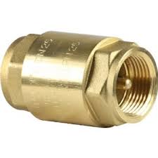
In each of water inlet and outlet pipes of the heat exchanger, a shut-off valve will be installed next to the corresponding sleeve.

The heat exchangers used in sanitary water circuits will be made of stainless steel or copper.

The design head loss in the heat exchanger shall not exceed 3 m / ac, both in primary and in secondary circuit.

Solar exchangers type:

Plate heat exchanger: This type of heat exchanger is made up of a series of corrugated metal plates, joined together in a frame by pressure and sealed by a gasket. Plates form a series of interconnected corridors through which working fluids circulate. These fluids are powered by pumps.

In order to choose correct plate heat exchanger for the system, it is necessary to consult the manufacturer’s guidelines. However, it is recommended that the thermal power to be transferred (in Kw) is equal to 2/3 of the collecting surface (in m2).

Ver las imágenes de origen

Double wrap exchanger: this system consists of a tank in which the secondary fluid (hot water) is accumulated and which has a double wall through which heat transfer fluid circulates, giving heat to domestic hot water.

Exchanger’s operating conditions dictate the choice of its material, which is usually carbon steel or alloy steels. Minimum exchange surface must be between 1/4 and 1/3 of useful collectors surface. However, there is a geometric limit to its use, which is given by housing dimensions. For a certain range of measurements, exchange surface can become less than a quarter collector surface. For volumes greater than 750 liters, the necessary exchange surface (which is the accumulator wall) is increasing and could result in very high accumulators for which it would be necessary to have a suitable machine room.

Ver las imágenes de origen

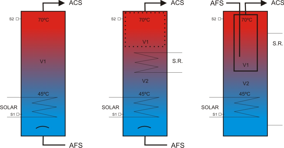
Coil exchanger: is made up of a tube that is submerged in a tank where the secondary fluid accumulates. The primary or heat transfer fluid circulates inside the tube, giving heat to the secondary fluid.

According tube shape they are distinguished:

Helical coil exchanger. The spiral wound tube that carries heat transfer fluid is submerged inside accumulator at the bottom.
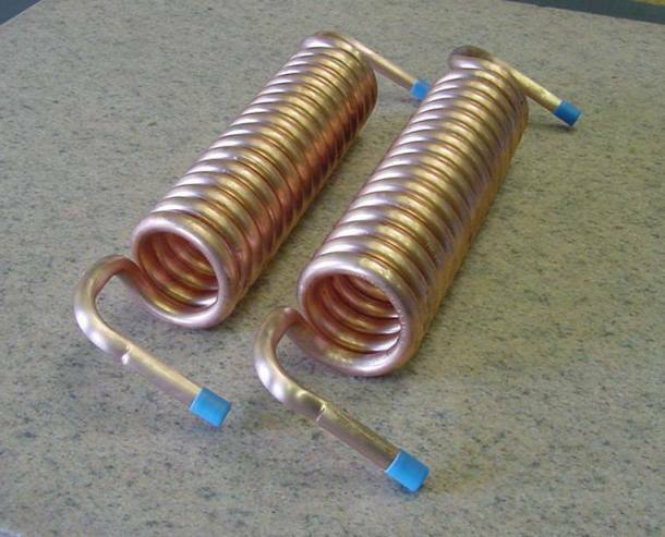
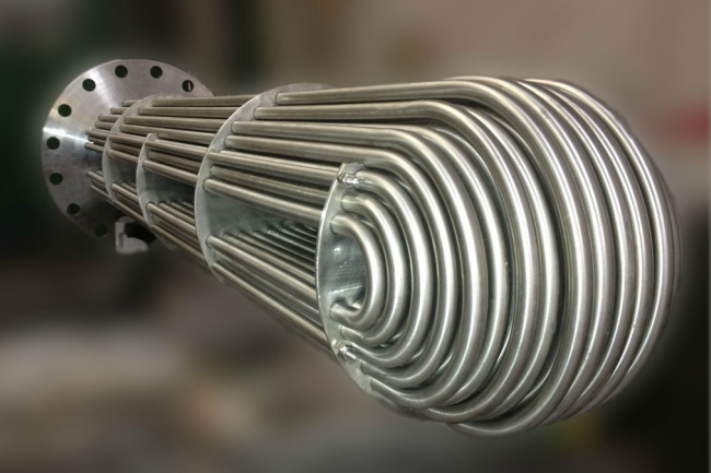
Ver las imágenes de origen

Tube bundle coil exchanger. They are commonly used to obtain ACS. Primary fluid circulates through several tubes, not one as in the helical. Liquid flows inside coil by forced circulation, while outside the fluid in contact with coil is renewed by natural circulation.

Ver las imágenes de origen

To know if a coil heat exchanger is suitable for use in solar applications, its minimum exchange surface must be between 1/4 and 1/3 of collectors useful surface.

The exchange surface of a helical coil or tube bundle will be the lateral surface of a cylinder based on outer section of the tube used and by height total length of the same. With this criterion it will be easy to size a tubular exchanger.

Some recommendations:
– The coil must be placed in the lowest part of accumulator.
– If it is helical, distance between turns should be equal to 2 times outer diameter of the tube.
– If we use antifreeze in a proportion of up to 30%, exchange surface must be increased by 10%.

This content was extracted from the Solar Thermal Energy Technical-Commercial Manual and is part of Solar e-learning.

All you need is Sun. All you need is Sopelia.

Solar Energy Panama

Panama’s National Energy Plan 2015-2050 suggests that up to 70% of country’s energy supply could be renewable in 35 years.

The generation matrix is highly dependent on hydroelectric resources (46% of installed capacity) and fossil fuels (42%) making Panama highly dependent on oil price evolution (it is a net importer) and rainfall regime, affected by the El Niño weather phenomenon that in recent years has caused significant droughts, causing a shortage of hydroelectric supply.

In addition, Panama’s National Interconnected System (SIN), which is the backbone of the electricity sector, is highly conditioned by the enormous distance between generation centers (province of Chiriquí, in the western zone) and consumption (Panama City and canal hub).

The energy matrix diversification need, guaranteeing supply and reducing price volatility, as well as complying with international commitments acquired by Panama in the Paris Agreement, has led to renewable energy sources slight introduction (wind and solar) and introduced natural gas into generation matrix.

SolarLatam | Como Funciona | Solar Latam

The Public Services Authority (ASEP) regulated in 2012 the connection of clean private plants to national electricity grid, with bi-directional meters and the energy “netting” to satisfy electrical consumption of each participant and sell the surplus.

Distributed rooftop solar generation delivers real-time power during the day with an unproductive asset (the roofs) to achieve a minimum fixed cost of own power for 25 years, with proven technology and reliable supply during peak demand and nights, because user is not disconnected from network.

The growth potential in the country is evident, as individual and business decisions to generate clean and renewable energy accelerate.

Reality is that solar energy participation in national energy matrix is not relevant. It currently represents only 2% of electricity generation.

A report from the International Renewable Energy Agency (IRENA) in May 2018 suggests the following recommendations for Panama:

o Evaluate regulatory and financial incentives for solar and wind energy development;

o Develop a national strategy to improve planning and modeling of electrical systems with greater RE penetration;

o Identify new operating practices to increase network flexibility and reliability with a greater RE participation;

o Evaluate the regulatory interfaces between National Electricity Market (MEN) and Regional Electricity Market (MER);

o Examine how to develop the capabilities of Panama’s workforce to achieve 2050 renewable energy target;

o Develop a long-term plan for electric mobility and sector coupling.

By referring to this post you will get a 50% discount on Sopelia E-learning training that begins on April 20 next.

All you need is Sun. All you need is Sopelia.

Solar Accumulator Tanks

Accumulator is responsible for storing the thermal energy generated by the solar collectors.

It is essential in solar systems since periods of solar radiation and energy transfer do not usually correspond to periods in which hot water consumption takes place.

Storing energy using hot water is cheap, easy to handle, has a high heat capacity and is at the same time the consumption element in case of DHW (domestic hot water).

Accumulator type depends on the application: domestic hot water, air conditioning, heating or industrial use.

Ver las imágenes de origen

Most common are:

Domestic hot water accumulators: they must be able to withstand high levels of pressure and expected working temperatures, not suffer deterioration due to corrosion phenomena and compulsorily comply with requirements for storing drinking water.
They are generally offered with capacities of 100 to 5,000 liters of accumulation.

Inertia accumulators: they are used as a heat accumulator for heating systems or for large DHW installations. They fulfill the function of buffer for heat or cold storage. They act as hydraulic memory between heat production and release.
They are generally offered with capacities of 500 to 5,000 liters of accumulation.

Combined accumulators: they combine accumulation of DHW and accumulation of heating.
In the same accumulator, for example, 175 liters of DHW accumulation and 600 liters of heating accumulation are combined.
They are generally offered with capacities from 175 to 250 liters for DHW accumulation and 500 to 2,000 liters for heating accumulation.

The most used materials accumulators’ construction are:

Steel: it needs internal treatments based on epoxy or vitrified to avoid corrosion.

Stainless steel: it is without a doubt the best material.

Galvanized steel: accumulation temperature must not exceed 65º C.

Reinforced fiberglass: resists corrosion, weighs little and is easy to maintain, but withstands low temperatures (60º C maximum).

Plastics: it has similar qualities to fiberglass.

Aluminum: it is not advisable due to corrosion problems.

In addition to interior treatments, accumulators incorporate corrosion protection devices.

One of the problems caused by corrosion is that rust and sediments favor the legionella development.
It is essential to avoid it by building accumulators with noble materials such as some type of stainless steel and / or combination of some inner lining and a cathodic protection system.

Accumulators are usually cylindrical in shape and have a vertical dimension greater than horizontal one to favor thermal stratification of the inside water.
Hottest water from top will be located in the extraction zone towards consumption or towards conventional support system. Coldest water is in the lower part of the tank, which will be from where it will be pushed towards solar collectors.
In this way, we operate the collectors at the minimum possible temperature, increasing their performance.

Ver las imágenes de origen

Accumulation volume size depends mainly on three factors:

1 • Installed collectors surface

As a general criterion for DHW, an accumulation volume between 50-100 liters per m2 of solar collector is recommended.
Higher values do not lead to a significant increase in solar energy use, and accumulator cost increases.
In contrast, smaller sizes increase the temperature, thus decreasing collectors’ efficiency.
For small DHW systems production, solar tank capacity should be equal to daily hot water consumption.

2 • Operating temperature

This will determine type of stratification device, as well as insulator thickness to be used, depending on maximum losses that are admissible considered.

3 • Offset between collection – storage and consumption

Accumulation volume will be a function of lag between collection – storage and consumption period, which can be:

* Coincidence between collection period and consumption period (case of preheating a boiler in a continuous process).
In this case, accumulator specific volume will be 35-40 liters / m2.

* Offsets between collection and consumption not exceeding 24 hours (heating of sanitary water in multi-family homes, hotels, etc.).
In this case, volume will be 60-90 liters / m2.

* Offset between usual and periodic collection and consumption for more than 24 hours and less than 72 hours (heating of domestic hot water in industrial processes, etc.).
In this case, volume will be 75-100 liters / m2.

* Offsets between collection and consumption greater than 72 hours (heating of sanitary water in second home, on weekends.).
In this case, volume will be determined by balancing energy losses and gains and insulation optimizing.

This content was extracted from the Solar Thermal Energy Technical-Commercial Manual and is part of Solar e-learning.

All you need is Sun. All you need is Sopelia.

Nicaragua Solar Thermal

Undoubtedly, the emblematic project, in terms of thermal solar energy, is the system inaugurated on October 9, 2018 at the Doctor Alejandro Dávila Bolaños Military Hospital in Managua.

With an investment of US $ 4.3 million financed through a soft loan from Oesterreichische Kontrollbank and Raiffeisen Bank International and with the United Nations Agency for Industrial Development (UNIDO), and the National Production Center more Clean from Nicaragua support; This system provides 30% of the demand required for air conditioning and 100% of the demand for hot water (used in various hospital operational functions, such as: personal, patients and doctors hygiene, food cleaning and preparation in the kitchen, for laundry area, among others).

The solar system was installed in a 4,450 square meters area, is composed of 338 thermal solar panels and will have an environment positive impact eliminating more than 1,100 tons of dioxide carbon emission each year.

It is the second largest system in the world, the largest in hospitals and unique in Latin America.

Resultado de imagen de energía solar hospital militar nicaragua

Despite the increase in systems number, solar energy only represents 1% of Nicaragua’s energy matrix.

There is a feeling that decision making is more market focused and not as a development issue.

The key is to associate the solar technology development with economic activities, establish a relationship between water resources, renewable energy and food security and base on renewable energy the climate change adaptation.

Currently solar energy provides energy security in contrast, for example, to energy supply via hydroelectric dams that depends on rains that are varying more and more throughout the region due to climate change.

Resultado de imagen de energía solar térmica nicaragua

Energy sources diversification becomes indispensable and has led to a solar energy investments growth.

This has been possible due to public resources contribution to support this technology development, the political commitment and the role carried out by the private initiative.

In this sense, it is worth highlighting the work that the BID is doing in the region.

In spite of advances, the pending subject continues being the regional energetic integration.

An energy networks extension at regional level would help lower costs and a energy supply diversification would guarantee greater energy security.

All you need is Sun. All you need is Sopelia.

Solar Thermal Pipes

Connection of different components of the solar system is carried out with pipes, until the necessary hydraulic circuits are formed.

Normally, materials used for primary circuit pipes are copper, black steel and plastic materials

The cross-linked polyethylene pipes can be used without problems, provided that manufacturer guarantees their use above 120º C.

Galvanized steel should not be used in primary circuits (from collectors to storage) due to the strong deterioration that zinc protection undergoes with temperatures above 65º C.

In general, the fluid velocity must not exceed 1.5 or 2 m / s in the primary circuit.

Pipes diameter can be selected so that fluid flow velocity is less than 2 m / s when pipe runs through inhabited places and at 3 m / s when the route is outside or by uninhabited places.

When steel is used in pipes or fittings, working fluid pH should be between 5 and 9.

Pipes dimensioning will be carried out in such a way that the load unit loss in pipes never exceeds 40 mm of water column per linear meter.

The circuit load total loss must not exceed 7 m of water column.

The maximum load loss is applicable to primary circuit and secondary circuit. If it were larger, we would be obliged to choose the immediately superior pipe diameter.

For pools heating, PVC pipes are used, which can have large diameters without a significant additional cost.

All piping networks must be designed in such a way that they can be emptied partially and totally, through an element that has a minimum nominal diameter of 20 mm.

Ver las imágenes de origen

For pipeline selection, following aspects must be taken into account:

1º Fluid compatibility:

Materials to be used for ACS circuits may be:

• Metallic:

– Galvanized steel, UNE-EN 10.255 M series (only in cold water).
– Stainless steel, UNE-EN 10.312, series 1 and 2.
– Copper, UNE-EN 1.057.

• Thermoplastics:

– Non-plasticized polyvinyl chloride (PVC), UNE-EN 1.452.
– Chlorinated polyvinyl chloride (PVC-C), UNEEN ISO 15,877.
– Polyethylene (PE), UNE-EN 12.201.
– Crosslinked polyethylene (PE-X), UNE-EN ISO 15.875.
– Polybutylene (PB), UNE-EN ISO 15.876.
– Polypropylene (PP) UNE-EN ISO 15.874.
– Multilayer polymer / aluminum / polyethylene (PE-RT), UNE 53.960 EX.
– Multilayer polymer / aluminum / polyethylene (PE-X), UNE 53.961 EX.

Aluminum tubes and those whose composition contains lead are expressly prohibited.

2º Work pressure:

A minimum pressure of 1 bar and a maximum of 5 bar must be guaranteed at all points of consumption; so you can take 5 bars as pressure for series selection.

Although tanks safety valves are usually set at 8 bar this is a more appropriate design pressure.

3º Working temperature:

Hot water and heating pipes should remain stable with system working temperatures, sporadically be able to reach temperatures close to 95 ° C and continue to resist with a life expectancy of at least 50 years.

4º Charge loss:

When a liquid circulates inside a straight tube, its pressure decreases linearly along its length, even though it is horizontal.

That pressure drop is called charge loss.

Valves, constrictions, elbows, direction changes, derivations, etc. they cause load local or singular losses that must also be taken into account.

Total load loss, which is the sum of linear load loss and singular load losses, must be determined.

Ver las imágenes de origen

5º Pipe size:

To calculate pipe size we start from the flow data.

We must determine pipeline minimum diameter (ie the most economical) without load loss exceeding a reasonable limit, so as not to be forced to use a higher power pumping group with the consequent energy waste.

We know from experience that fluid circulation speed maximum recommended is approximately 1.5 m / s if it does so continuously (primary circuits) and 2.5 m / s if it does so at intervals (secondary consumption circuits).

It is also recommended (or required) that pressure drop for each tube linear meter does not exceed 40 mm ca.

These 2 conditions impose a lower limit on pipe diameter.

It is usual to start from an estimated diameter based on experience in similar systems and verify that choice implies values of load loss and speed lower than recommended maximums.

If this is not the case, verification should be repeated for an immediately larger diameter.

If on contrary, we can select a smaller diameter than initial one, we will save on material; especially if circuit has a considerable length.

As a first approximation, we can resort to following formula:

D = j C 0.35

Being:
D diameter in cm
C flow in m3 / h
j 2,2 for metal pipes and 2,4 for plastic pipes.

Initial estimation, whatever method used, must be verified by using load loss tables or abacuses.

There are tables and specific abacuses for each type of material (copper, steel, plastics) that allow to determine load loss due to friction and fluid speed in the tubes.

This content was extracted from the Solar Thermal Energy Technical-Commercial Manual and is part of Solar e-learning.

All you need is Sun. All you need is Sopelia.

Solar Nicaragua

Nicaragua claims to be less dependent on thermal energy, which is produced based on petroleum derivatives, and therefore executes solar development projects on the Caribbean coast and in country rural areas.

One of the first initiatives back in 2009 was the Euro Solar program, which benefited 42 communities (7,000 families) in the North Atlantic Autonomous Region (RAAN), generating electricity for health services, education and Internet and telephony communication in community centers.

Then Nicaragua depended 80% of energy generated from petroleum derivatives.

Due to its location, Nicaragua is a country with high potential for solar energy use and at same time has one of the lowest electrification rates in the region.

In 2015, with the objective of bringing electricity to North Atlantic Autonomous Region communities and interior municipalities, the Mulukukú Electric Substation was built, which included 200 kms of transmission lines construction between Siuna and Puerto Cabezas (RAAN), where 1,500 solar modules and several electrical substations were installed.

Nicaragua’s largest photovoltaic park, Astro Solar Plant, was installed, which with 3 MW in the Tipitapa municipality supplies electricity to the Zona Franca Astro industrial park.

Ver las imágenes de origen

Energy generation from renewable sources development had important fiscal benefits thanks to Law 901:

Payment exemption of Import Tariffs (DAI) and Value Added Tax (VAT), on machinery, equipment, materials and supplies used for pre-investment and construction work, including the construction of subtransmission lines necessary to energy transport from generation plant to National Interconnected System (SIN).

Payment exemption of Income Tax (IR) for a period of 7 years from project entry into commercial operation.

Payment exemption of Municipal Taxes on real estate, sales and registration for a period of 10 years from project entry into commercial operation.

Resultado de imagen de energía solar nicaragua

Renewable energy in Nicaragua continues to advance smoothly. In 2006, renewable energy represented only 25% of national energy matrix, mainly hydroelectric and geothermal. Until December 2018, renewable energies accounted for 59% of national energy matrix, although in some moments of last year it reached up to 80% of total generation.

Regarding renewable generation contribution by sector, it is estimated that biomass with sugar cane residues contributed 216 MW; hydroelectric energy 150 MW; geothermal 154 MW; wind energy 186 MW; and solar 13 MW. Geothermal energy has been considered the energy of the future of Nicaragua because compared to wind and hydroelectric, it is more firm and constant in its level of generation and has great potential.

Despite these advances, Nicaragua continues to be the country with the most expensive Central American energy in industrial sector. Only those who consume less than 150 kWh per month pay for cheap energy, which mainly benefits the residential consumer.

The origin of these high prices is in the need and urgency of government income, which are obtained in national energy tariff and used to pay internal and external debts.

The main obstacles to distributed solar generation development in Nicaragua are the high initial investment represented by a system for most Nicaraguans and the lack of a law that promotes and regulates electricity sale from small photovoltaic systems connected to the grid.

It is necessary to amend Law 532 or adopt a new law that establishes a reasonable sales rate, incentives for producers, network operators and consumers, as well as simplifying bidding processes in the contracting of energy for small residential systems and the industrial and services sectors.

Number of renewable energy professionals increases every year. New generations are more aware of environment damage that has been done and of solar energy potential. This new Nicaraguan generation must work to reduce energy prices and take advantage of solar energy to provide Nicaragua with a more sustainable and just future.

All you need is Sun. All you need is Sopelia.

PV Modules Support Structure

Regarding situation of photovoltaic modules, there are the following general possibilities:

Flooring: It is the most usual way of installing modules groups (especially in solar farms) and has great advantages in terms of wind resistance, accessibility and ease assembly.
However, it is more susceptible to being buried by snow, flooding or being broken by animals or people.

Ver las imágenes de origen

Pole: very used in small dimension systems, if it has a mast. It is the typical assembly type of isolated communication equipment or lampposts feeding.

Ver las imágenes de origen

Wall: good anchor points must be available on a built building. Accessibility can present some problems.

Ver las imágenes de origen

Roof: one of the most common because generally enough space is available. It also presents problems of snow cover and risks in roof fasteners waterproofing.

Ver las imágenes de origen

If system is located in an urban area, most common is to place the module on the roof.

In structure assembly, roof sealing must be ensured by waterproofing elements use.

A study must also be carried out to determine if ceiling will support modules and support structure weight.

However, main factor when fixing the structure is wind strength. Structure must withstand winds of at least 150 km / h.

On terraces or floors, the structure should allow a minimum height of the module of about 30 cm. In mountain areas or where there is abundant snowfall, it must be higher.

The structure and supports should preferably be anodized aluminum, stainless steel or galvanized iron and stainless steel fasteners.

Anodized aluminum is lightweight and highly resistant.

Stainless steel is suitable for very corrosive environments and has a longer useful life but its cost is high.

Galvanized iron structures offer good protection against external corrosive agents with the advantage that zinc is chemically compatible with lime and cement mortar, once these are dry.

Structures come in kits or standard profiles that are on the market and a specific system structure can be built.

Supports designed for a specific solar module are usually cheaper than those manufactured in order to be able to hold any type of module. However, it will surely be the latter that will end up developing in greater numbers in near future.

Normally, a solar modules support has the following characteristics: it has a plate provided on its upper face with quick coupling means for modules and one or more holes for the screws to be introduced and thus join the plate to the support. The support also has fastening means attached to plate lower face for fastening to lower structure.

Orientation will always be towards the equator and the following inclinations are recommended:

Systems with priority function in winter (eg: mountain lodge): 20º higher than place latitude.

Systems with uniform operation throughout the year (p.e .: home electrification): 15º greater than place latitude.

Systems with priority operation in spring and summer (p.e .: campings): same as place latitude.

Systems whose objective is to produce the greatest amount of energy throughout the year (eg: connection to the grid): 85% of place latitude.

The reason for inclination increasing, compared to that recommended for solar thermal collectors, is that generally in the case of photovoltaic systems there is no auxiliary energy system and it is necessary to capture all the energy possible in the most unfavorable period (winter).

Sopelia has developed Solar Layout, the Android App that allows you to obtain the inclination, orientation and distance between rows of photovoltaic modules at the installation site.

This content was extracted from the Solar Photovoltaic Energy Technical-Commercial Manual and is part of Solar e-learning.

All you need is Sun. All you need is Sopelia.

Solar Thermal System Protection

The correct design of a solar thermal system involves foreseeing all the circumstances that may damage it and applying strategies that can prevent breakdowns that shorten its useful life.

There are basically 5 aspects to keep in mind:

I-Frost protection:

Protection method will depend on the heat transfer fluid used and specific weather conditions of system site.

It is not enough to protect only the collectors. Outer pipes must also be protected.

As anti-frost protection systems, following could be used:

1. Antifreeze mixtures: it is the most used solution to system protection from freezing danger.

2. Water circuits recirculation: this system is suitable for climatic zones in which periods of low temperature are of short duration.

3. Automatic drainage with fluid recovery: this system requires the use of a heat exchanger between collectors and accumulator to maintain hot water supply pressure in it. This solution is not recommended in case collector absorber is made of aluminum.

4. Outdoor drainage (only for prefabricated solar systems): this system is not allowed in custom solar systems.

5. Total system shutdown during winter: this solution is advisable for systems that are only used in summer and it should be taken into account that empty circuits are subject to greater corrosion risks.

6. Collectors heating by an electrical resistance.

7. Collectors capable of withstanding freezing: there are collectors on the market that have sufficient elasticity to withstand volume increase due to freezing.

8. Introduction in absorber circuit of elastic and watertight capsules containing air or nitrogen. By increasing pressure due to freezing, they are compressed avoiding failure due to breakage.

Ver las imágenes de origen

II-Overheating protection:

An excess of heat in solar thermal systems occurs when there is too much solar uptake in relation to energy obtained consumption. When this happens, collectors retain the heat that has not been evacuated and raise its temperature to levels that can be dangerous for system.

It is estimated that a heat transfer fluid e temperature xceeding 90 ºC becomes dangerous for the system.

Problem arises when, for reasons already mentioned, temperature rises too high in collectors and the heat transfer fluid circulating inside primary circuit begins to boil, expand and emit steam.

Both dilation and vaporization raise the pressure inside the primary circuit.

On the other hand, when heat transfer fluid begins to boil in the primary circuit, scale builds up on surfaces of the various components that deteriorate equipment.

In collectors overheating, 3 cases can occur:

1. Closed circuit with outdoor expansion vessel: steam produced goes outside. This can cause scale and risk of emptying part of circuit, forcing it to be filled before it is put into service.

2. Open circuit (consumption water passes through collectors): if boiling pressure exceeds network pressure, the produced steam will discharge into network contaminating the water.

3. Closed circuit and closed expansion vessel: when temperature rises, pressure rises and safety valve will open when it reaches a certain predetermined value.

Overheating risk in storage is lower and it can be said that it could only occur if system has high performance collectors (eg, vacuum tube collectors) and lacks a dissipation mechanism.

When water is hard (content of calcium salts between 100 and 200 mg / l), necessary precautions shall be taken so that working temperature of any point of consumption circuit does not exceed 60 ° C, without prejudice to necessary requirements against legionella application.

In any case, necessary means will be available to facilitate circuits cleaning.

In addition to safety elements there are other mechanisms to avoid overheating dangers:

• Use an organic fluid with a high boiling point.

• Angle of inclination of collectors higher than optimal to capture solar radiation preferably in winter. This ensures that the most perpendicular rays of summer fall with greater inclination on collector and take less advantage.

• Excess heat poured into the pool.

• Eaves. Through arrangement of strategically placed eaves it is possible to reduce the solar radiation that solar collectors support in summer.

• Cover collectors with covers.

• Heat sinks. These devices circulate superheated liquid through ducts to dissipate its heat in the air.
Some direct all the superheated flow of primary circuit to a unit where heat is dissipated with the help of fans (air heaters).
Others, however, are structures that are placed in each collector or battery of collectors and that dissipate only heat generated by the unit they are on. This type of heatsink works by gravity, without electronic components and is activated by means of thermostatic valves. It has the advantage that it continues to work in the event of a power cut.

Ver las imágenes de origen

III-Pressure resistance:

In case of closed systems, maximum working pressure of all components shall be taken into account. The component that has the lowest maximum working pressure is the one that will set the pattern for entire system.

In case of open consumption systems with network connection, maximum pressure of the same shall be taken into account to verify that all components of the consumption circuit support said pressure.

Ver las imágenes de origen

IV-Reverse flow prevention:

System installation must ensure that no relevant energy losses due to unintentional inverse flows occur in any hydraulic circuit of the system.

The natural circulation that produces the reverse flow can be favored when the accumulator is below the collector, so it will be necessary to take, in those cases, the appropriate precautions to avoid it.

In systems with forced circulation, it is advisable to use a non-return valve to avoid reverse flows.

Ver las imágenes de origen

V-Legionellosis prevention:

It must be ensured that water temperature in hot water distribution circuit is not lower than 50 ° C at the furthest point and before the necessary mixture for protection against burns or in the return pipe to accumulator. System will allow water to reach a temperature of 70 ° C. Consequently, the presence of galvanized steel components is not admitted.

Ver las imágenes de origen

This content was extracted from the Solar Thermal Energy Technical-Commercial Manual and is part of Solar e-learning.

All you need is Sun. All you need is Sopelia.