Tag Archives: energía solar térmica en latinoamérica

Solar Thermal Pipes

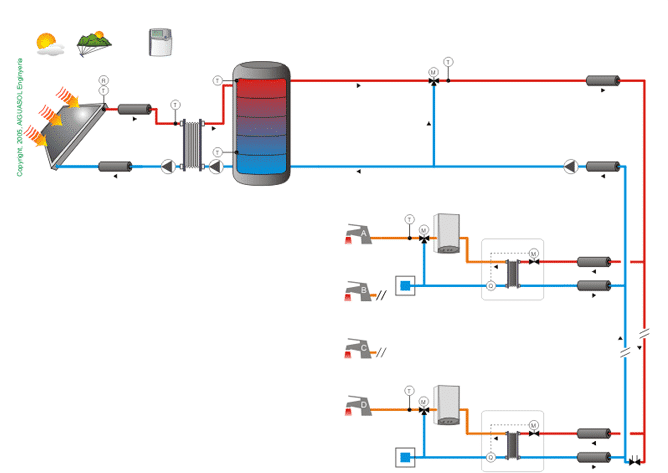
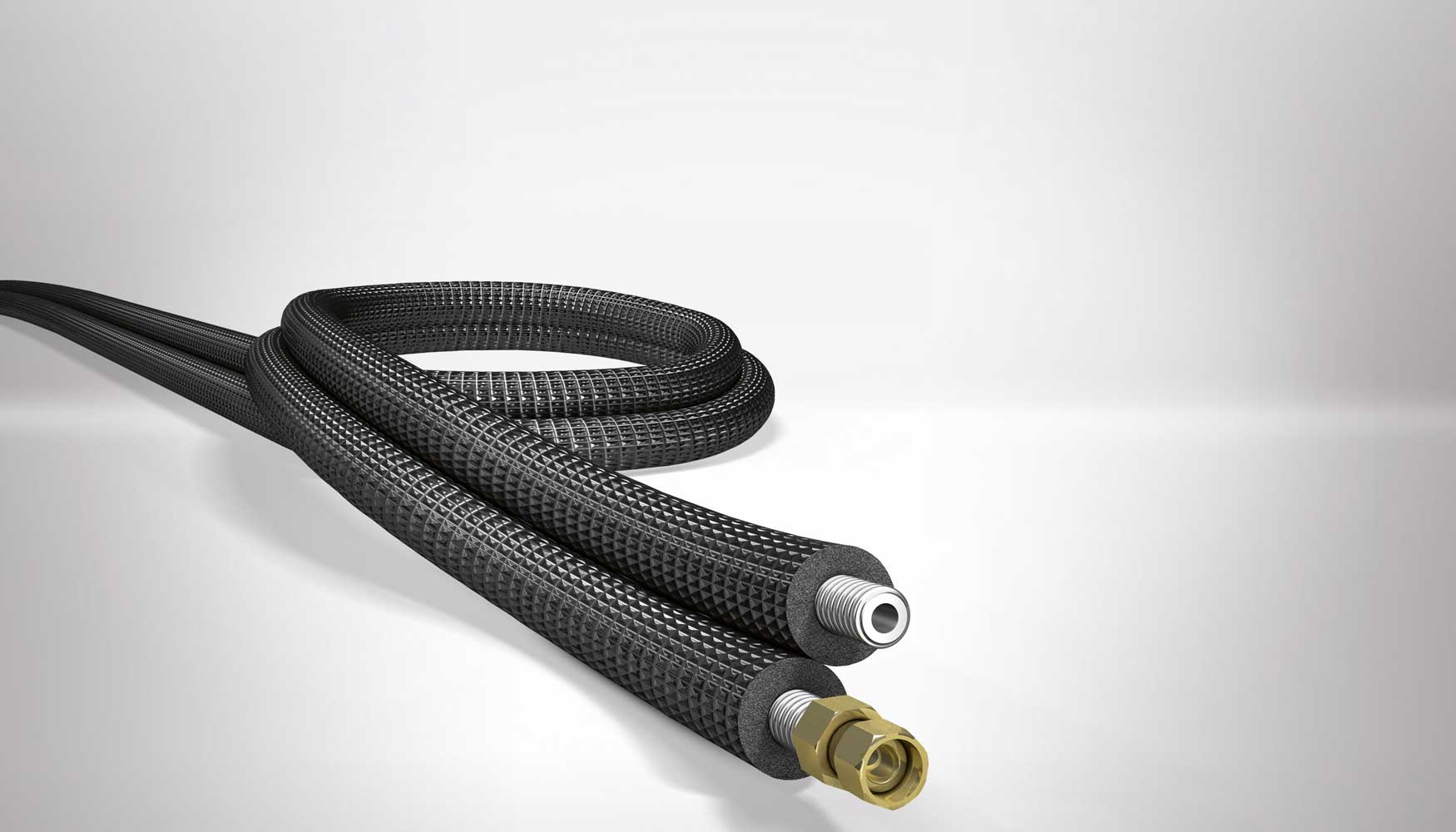
Connection of different components of the solar system is carried out with pipes, until the necessary hydraulic circuits are formed.

Normally, materials used for primary circuit pipes are copper, black steel and plastic materials

The cross-linked polyethylene pipes can be used without problems, provided that manufacturer guarantees their use above 120º C.

Galvanized steel should not be used in primary circuits (from collectors to storage) due to the strong deterioration that zinc protection undergoes with temperatures above 65º C.

In general, the fluid velocity must not exceed 1.5 or 2 m / s in the primary circuit.

Pipes diameter can be selected so that fluid flow velocity is less than 2 m / s when pipe runs through inhabited places and at 3 m / s when the route is outside or by uninhabited places.

When steel is used in pipes or fittings, working fluid pH should be between 5 and 9.

Pipes dimensioning will be carried out in such a way that the load unit loss in pipes never exceeds 40 mm of water column per linear meter.

The circuit load total loss must not exceed 7 m of water column.

The maximum load loss is applicable to primary circuit and secondary circuit. If it were larger, we would be obliged to choose the immediately superior pipe diameter.

For pools heating, PVC pipes are used, which can have large diameters without a significant additional cost.

All piping networks must be designed in such a way that they can be emptied partially and totally, through an element that has a minimum nominal diameter of 20 mm.

Ver las imágenes de origen

For pipeline selection, following aspects must be taken into account:

1º Fluid compatibility:

Materials to be used for ACS circuits may be:

• Metallic:

– Galvanized steel, UNE-EN 10.255 M series (only in cold water).
– Stainless steel, UNE-EN 10.312, series 1 and 2.
– Copper, UNE-EN 1.057.

• Thermoplastics:

– Non-plasticized polyvinyl chloride (PVC), UNE-EN 1.452.
– Chlorinated polyvinyl chloride (PVC-C), UNEEN ISO 15,877.
– Polyethylene (PE), UNE-EN 12.201.
– Crosslinked polyethylene (PE-X), UNE-EN ISO 15.875.
– Polybutylene (PB), UNE-EN ISO 15.876.
– Polypropylene (PP) UNE-EN ISO 15.874.
– Multilayer polymer / aluminum / polyethylene (PE-RT), UNE 53.960 EX.
– Multilayer polymer / aluminum / polyethylene (PE-X), UNE 53.961 EX.

Aluminum tubes and those whose composition contains lead are expressly prohibited.

2º Work pressure:

A minimum pressure of 1 bar and a maximum of 5 bar must be guaranteed at all points of consumption; so you can take 5 bars as pressure for series selection.

Although tanks safety valves are usually set at 8 bar this is a more appropriate design pressure.

3º Working temperature:

Hot water and heating pipes should remain stable with system working temperatures, sporadically be able to reach temperatures close to 95 ° C and continue to resist with a life expectancy of at least 50 years.

4º Charge loss:

When a liquid circulates inside a straight tube, its pressure decreases linearly along its length, even though it is horizontal.

That pressure drop is called charge loss.

Valves, constrictions, elbows, direction changes, derivations, etc. they cause load local or singular losses that must also be taken into account.

Total load loss, which is the sum of linear load loss and singular load losses, must be determined.
Ver las imágenes de origen

5º Pipe size:

To calculate pipe size we start from the flow data.

We must determine pipeline minimum diameter (ie the most economical) without load loss exceeding a reasonable limit, so as not to be forced to use a higher power pumping group with the consequent energy waste.

We know from experience that fluid circulation speed maximum recommended is approximately 1.5 m / s if it does so continuously (primary circuits) and 2.5 m / s if it does so at intervals (secondary consumption circuits).

It is also recommended (or required) that pressure drop for each tube linear meter does not exceed 40 mm ca.

These 2 conditions impose a lower limit on pipe diameter.

It is usual to start from an estimated diameter based on experience in similar systems and verify that choice implies values of load loss and speed lower than recommended maximums.

If this is not the case, verification should be repeated for an immediately larger diameter.

If on contrary, we can select a smaller diameter than initial one, we will save on material; especially if circuit has a considerable length.

As a first approximation, we can resort to following formula:

D = j C 0.35

Being:
D diameter in cm
C flow in m3 / h
j 2,2 for metal pipes and 2,4 for plastic pipes.

Initial estimation, whatever method used, must be verified by using load loss tables or abacuses.

There are tables and specific abacuses for each type of material (copper, steel, plastics) that allow to determine load loss due to friction and fluid speed in the tubes.

This content was extracted from the Solar Thermal Energy Technical-Commercial Manual and is part of Solar e-learning.

All you need is Sun. All you need is Sopelia.

Solar Thermal System Protection

The correct design of a solar thermal system involves foreseeing all the circumstances that may damage it and applying strategies that can prevent breakdowns that shorten its useful life.

There are basically 5 aspects to keep in mind:

I-Frost protection:

Protection method will depend on the heat transfer fluid used and specific weather conditions of system site.

It is not enough to protect only the collectors. Outer pipes must also be protected.

As anti-frost protection systems, following could be used:

1. Antifreeze mixtures: it is the most used solution to system protection from freezing danger.

2. Water circuits recirculation: this system is suitable for climatic zones in which periods of low temperature are of short duration.

3. Automatic drainage with fluid recovery: this system requires the use of a heat exchanger between collectors and accumulator to maintain hot water supply pressure in it. This solution is not recommended in case collector absorber is made of aluminum.

4. Outdoor drainage (only for prefabricated solar systems): this system is not allowed in custom solar systems.

5. Total system shutdown during winter: this solution is advisable for systems that are only used in summer and it should be taken into account that empty circuits are subject to greater corrosion risks.

6. Collectors heating by an electrical resistance.

7. Collectors capable of withstanding freezing: there are collectors on the market that have sufficient elasticity to withstand volume increase due to freezing.

8. Introduction in absorber circuit of elastic and watertight capsules containing air or nitrogen. By increasing pressure due to freezing, they are compressed avoiding failure due to breakage.

Ver las imágenes de origen

II-Overheating protection:

An excess of heat in solar thermal systems occurs when there is too much solar uptake in relation to energy obtained consumption. When this happens, collectors retain the heat that has not been evacuated and raise its temperature to levels that can be dangerous for system.

It is estimated that a heat transfer fluid e temperature xceeding 90 ºC becomes dangerous for the system.

Problem arises when, for reasons already mentioned, temperature rises too high in collectors and the heat transfer fluid circulating inside primary circuit begins to boil, expand and emit steam.

Both dilation and vaporization raise the pressure inside the primary circuit.

On the other hand, when heat transfer fluid begins to boil in the primary circuit, scale builds up on surfaces of the various components that deteriorate equipment.

In collectors overheating, 3 cases can occur:

1. Closed circuit with outdoor expansion vessel: steam produced goes outside. This can cause scale and risk of emptying part of circuit, forcing it to be filled before it is put into service.

2. Open circuit (consumption water passes through collectors): if boiling pressure exceeds network pressure, the produced steam will discharge into network contaminating the water.

3. Closed circuit and closed expansion vessel: when temperature rises, pressure rises and safety valve will open when it reaches a certain predetermined value.

Overheating risk in storage is lower and it can be said that it could only occur if system has high performance collectors (eg, vacuum tube collectors) and lacks a dissipation mechanism.

When water is hard (content of calcium salts between 100 and 200 mg / l), necessary precautions shall be taken so that working temperature of any point of consumption circuit does not exceed 60 ° C, without prejudice to necessary requirements against legionella application.

In any case, necessary means will be available to facilitate circuits cleaning.

In addition to safety elements there are other mechanisms to avoid overheating dangers:

• Use an organic fluid with a high boiling point.

• Angle of inclination of collectors higher than optimal to capture solar radiation preferably in winter. This ensures that the most perpendicular rays of summer fall with greater inclination on collector and take less advantage.

• Excess heat poured into the pool.

• Eaves. Through arrangement of strategically placed eaves it is possible to reduce the solar radiation that solar collectors support in summer.

• Cover collectors with covers.

• Heat sinks. These devices circulate superheated liquid through ducts to dissipate its heat in the air.
Some direct all the superheated flow of primary circuit to a unit where heat is dissipated with the help of fans (air heaters).
Others, however, are structures that are placed in each collector or battery of collectors and that dissipate only heat generated by the unit they are on. This type of heatsink works by gravity, without electronic components and is activated by means of thermostatic valves. It has the advantage that it continues to work in the event of a power cut.

Ver las imágenes de origen

III-Pressure resistance:

In case of closed systems, maximum working pressure of all components shall be taken into account. The component that has the lowest maximum working pressure is the one that will set the pattern for entire system.

In case of open consumption systems with network connection, maximum pressure of the same shall be taken into account to verify that all components of the consumption circuit support said pressure.

Ver las imágenes de origen

IV-Reverse flow prevention:

System installation must ensure that no relevant energy losses due to unintentional inverse flows occur in any hydraulic circuit of the system.

The natural circulation that produces the reverse flow can be favored when the accumulator is below the collector, so it will be necessary to take, in those cases, the appropriate precautions to avoid it.

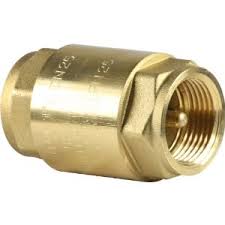
In systems with forced circulation, it is advisable to use a non-return valve to avoid reverse flows.

Ver las imágenes de origen

V-Legionellosis prevention:

It must be ensured that water temperature in hot water distribution circuit is not lower than 50 ° C at the furthest point and before the necessary mixture for protection against burns or in the return pipe to accumulator. System will allow water to reach a temperature of 70 ° C. Consequently, the presence of galvanized steel components is not admitted.

Ver las imágenes de origen

This content was extracted from the Solar Thermal Energy Technical-Commercial Manual and is part of Solar e-learning.

All you need is Sun. All you need is Sopelia.

Mexico Solar Thermal

As in most Latin American countries, in Mexico, statistics in solar thermal energy field are not up-to-date and renewable energies prospects do not include this source of generation.

In Mexico, in 2010, solar systems to heat water were installed in an equivalent area of 272,580 m2, reaching an accumulated area of 1,665,502 m2.

According to estimates, in next 4 years almost double the production area by solar thermal energy.

Although we do not find data about current installed capacity in Mexico, we can conclude that this type of energy has had a great growth in recent years and that it is likely that the installed capacity has doubled again.

Due to country average radiation levels, a solar thermal installation for domestic hot water has become a very profitable investment in Mexico, since water heating causes the greatest gas consumption and with this application, gas use is reduced by up to 80% in regions with higher radiation.

Recently there has been a noticeable decrease in prices of solar equipment for domestic hot water.
The factors that allow this to happen are imports, easy manufacturing, technology maturity and competitiveness between national and international companies that offer this type of equipment.

In Mexico, there are important companies that manufacture low temperature thermal solar energy equipment. The first began in 1940 in Guadalajara.

Several government programs have promoted low cost acquisition of solar heaters by residents of areas where the gas network does not reach.

Other solar thermal energy applications that have increased considerably are swimming pools conditioning and water heating for industrial processes.

Ver las imágenes de origen

Hermosillo was one of the first states to adopt this type of technology for industrial processes in Mexico.

A cement company uses a thermal 291 KW equipment to operate a 75 tons of single effect cooling system. This was the first air conditioning system based on renewable energy in Latin America. The parabolic cylindrical collectors are located on the roof and on one side of corporate building; it operates in a range from 70 ° C to 95 ° C.

Other systems have been installed for generating heat purpose.

Mexican companies have commercially developed parabolic-linear solar concentrators to generate thermal energy between 50 ° C and 200 ° C. These systems are used mainly in food sector.

Some of the companies that currently have this alternative energy generation in the country are:

– Food company: installation of 80 solar concentrators for process heat generation and absorption chiller supply.

– Dairy company: installation of 70 solar concentrators for direct heat input in dairy products processing.

– Egg producing company: installation of 80 solar concentrators for boiler preheating.

Imagen relacionada

Despite advances, there is still much room for solar thermal technology development in Mexico.

The final impulse could come from special financing lines implementation, since for a large population sector initial system investment is still very high.

All you need is Sun. All you need is Sopelia.

Solar Collectors Clamping And Anchoring

Proposed solution must comply, in order of importance:

– That it’s enough safe .
– That its cost be as low as possible.
– Speed and simplicity in assembly.

A method currently used is anchoring by chemical plug.

There are structures are of different materials. The most commonly used are aluminum and stainless steel.

Manufacturers usually sell the collector with its structure, although you can always design your own structure.

It is not advisable to transfer building cover with the anchor (it can cause leaks).

In case of large installations, a pre-assembly work can be carried out to make assembly on roof faster and cheaper.

In near coast areas, structure must be hot dip galvanized.

Screws should be made of stainless steel or corrosion resistant material.

Anchoring type will be based on:

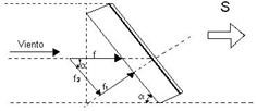
1) Wind forces that must endure. If collector is South oriented (we are in the Northern Hemisphere), wind that represents a risk is that coming from North (it is the inverse if we are in the Southern Hemisphere), which will exert tensile force on the anchors. The South wind will exert compressive force, not so dangerous. Wind force on a surface is:

f = P. S. sen2α
f = Weight to counteract wind strength.
P = wind load (Kg / m2).
S = collector surface (m2).
sin2α = angle of inclination sine.

Wind force is decomposed into f1, which incites perpendicularly to collector surface and in f2, which does it in parallel.

f1 force is at the end what counts and what is obtained from previous formula.

2) Collectors orientation and inclination. Collectors are oriented towards Ecuador. Normally, if we are in Southern hemisphere, they are oriented towards North and vice versa. Deviations of up to 20% with respect to optimal orientation do not significantly affect system performance and thermal energy contributed.

Collector’s inclination angle will depend on solar equipment use. Orientates inclinations:

• All year use (H.W.S.): inclination angle equal to geographical latitude.

• Winter preferably use (heating): inclination angle equal to geographical latitude + 10º.

• Summer period preferred use (outdoor pools heating): inclination angle equal to geographical latitude – 10º.

Variations of ± 10º with respect to optimum inclination angle practically do not affect performance and useful thermal energy provided by solar equipment.

3) Collecting surface must be free of shadows. In the most unfavorable day of use period, installation must not have more than 5% of useful surface area covered by shadows.

Projected shadows practice determination is made observing environment from collector´s lower edge midpoint, taking the North-South line as a reference.

By making an angular sweep on both sides, we will try to locate nearby obstacles with an angular height greater than 15º / 25º.

A more accurate determination of possible shadows can be made using system sizing software based on simulation methods.

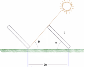
4) Minimum distance between collectors. Separation between collectors rows must be established so that at solar noon of most unfavorable day (minimum solar height) of use period, the shadow of upper edge of a row will be projected, at most, on lower edge of following row.

The formula of minimum distance between collectors is:

DT = L (senα / tan H + cosα)
H is the minimum solar height, which is:
H = (90º – latitude place) – 23.5º
L is collector´s height

If collector’s rows were arranged on a non-horizontal surface, expression would become:

DT = L ((sin (α – β) / tan (H + β) + cos (α – β))

α is still collector inclination angle respect to horizontal.

β is roof inclination angle respect to horizontal. It is positive if cover inclination angle direction coincides with that of collector; and with a negative value otherwise.

5) Finally, calculations must be carried out to ensure that cover or support will be able to support collectors weight, and that of the tank in case of thermosiphon and compact systems.

The R + D + I area of Sopelia has developed Solar Layout, the mobile app that allows collectors and modules to be optimally located at installation site.

All you need is Sun. All you need is Sopelia.

Free Solar Tools (III)

On Internet we can find free tools for basic or low complexity solar systems dimensioning and for certain components or accessories estimation.

Sopelia research team has carried out an exhaustive search and testing from which a new corporate website section called Free Solar Tools has been created.

Selected tools were classified into 4 categories.

Today we will analyze the third of them: Solar Thermal.

In first category we have already analyzed tools to obtain data about solar resource and other variables to be considered in energy estimation solar system will provide in our location.

In the second category we have analyzed tools to calculate the “load”, ie the energy demand to be met.

Now we are going to analyze tools to solar thermal system dimensioning and others to estimate individual components of a system.

The order of the tools is not random. We have prioritized the most intuitive, the most universal and those that can be used online without download.

For this third category our selection is as follows:

1) Solar Thermal Calculator

Approximate calculation tool from which budget, production data and system performance study is automatically obtained.

A Navigation Guide and Manuals can be found at page bottom.

Resultado de imagen de calculadora solar térmica

2) Simulation for Solar Thermal System Pre-design

Online application based on the TSOL software that allows solar energy system simulating to ACS and ACS + heating contribute.

Available in German, English, Spanish and French.

Resultado de imagen de simulación solar térmica

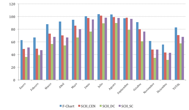
3) Solar Fraction Calculation

Free download program developed by IDAE (Institute for Energy Diversification and Saving) and ASIT (Solar Thermal Industry Association) that allows to define a wide variety of solar systems introducing a minimum of project parameters, associated to each system configuration; and in this way, obtain solar system coverage on ACS and pool conditioning energy demand.

Resultado de imagen de fracción solar térmica

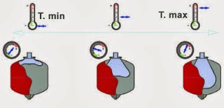
4) Solar Expansion Vessel Calculation

Tool developed to calculate solar expansion vessel volume.

Volume values (total circuit, solar collectors, pipes), Maximum system temperature (ºC), Glycol concentration (%), Height between expansion vessel and system highest point (minimum value 1 Bar) and safety valve Pressure setting must be introduced.

Resultado de imagen de cálculo vaso expansión solar

5) Thickness Insulation Pipes Calculation

Calculator that allows to estimate minimum and more economical water pipes insulation thickness.

Pipe Grade and Size, Insulation Material, Humidity and Temperature (Internal and Ambient) must be entered.

Resultado de imagen de aislamiento tubería solar

All you need is Sun. All you need is Sopelia.

Other Thermal Collectors

We have already talked about flat solar collectors and vacuum tube collectors.

Air collectors are also found in collectors without concentration category.

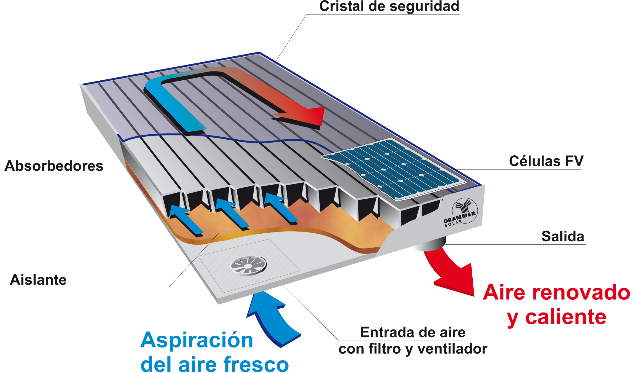
They are flat and their main characteristic is to have air as heat transfer fluid.

They do not have a maximum limit temperature (convective processes have less influence on the air) and work better in normal circulation conditions, but in contrast they have a low heat capacity and heat transfer process between plate and fluid is not good.

Its main application is heating.

Externally it is not possible to distinguish an air collector from a water collector. It is in the absorber where greatest differences are found. It has a rough shape and lacks the classic pipe of water collector ducts. The air circulates freely on absorber surface collecting the heat that it transforms.

Being a technology that has not been widely disseminated until now, there is no standardized solar collector model and each manufacturer makes its own model.

Resultado de imagen de colector solar de aire

There are also conical or spherical thermal solar collectors.

Their main characteristic is that they simultaneously constitute collection and storage unit.

Its catchment surface is conical or spherical with a same geometry glass cover. With this form it is achieved that illuminated surface throughout the day, in shade absence, is constant.

Their installation is simple, but they present water stratification problems and useful catchment surface is small.

Its main application is sanitary hot water in single-family homes production and in very benign climates, since large storage surface, weather exposed, causes great energy losses.

Resultado de imagen de colector solar cónico o esférico

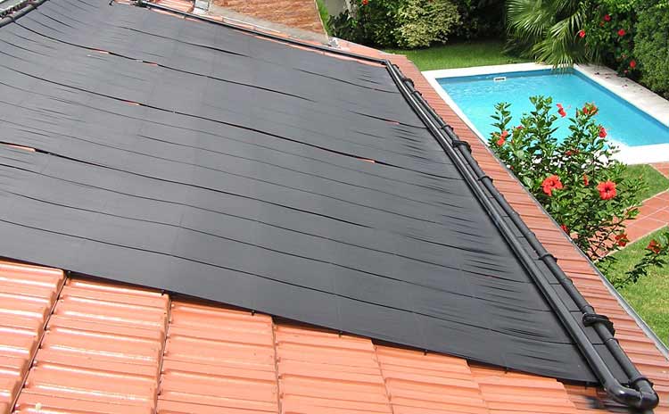
Finally, in collectors without concentration category, we find outdoor swimming pools solar collectors.

They are made of rubber, polypropylene or polyethylene; and incorporate in their manufacturing process substances that protect them from plastics natural tendency to degrade under ultraviolet rays action.

They also carry other additives to protect them from chemical agents used in pool water purification. They have an acceptable night frosts resistance.

They are used mainly to heat pools water and thus be able to prolong its use for several more months.

These collectors do not have cover, neither with housing nor with insulating material. They are constituted by naked plate collector. This is because working temperature will not exceed 30ºC in any case and at this low temperature, radiation and conduction losses are very small, making it possible to dispense with covers and insulation.

It is not necessary to use any type of heat exchanger or accumulator, because pool water flows directly through collectors.

They need a frame because they are usually not rigid, but they can also be placed directly on a roof, or even on the ground. By being flexible, absorb surface irregularities on which they rest.

These equipment enjoy an approximate 10 years lifespan. They need little maintenance and there is little risk of corrosion, as they are synthetic.

Resultado de imagen de colector solar piscinas

The second major group is that of solar collectors with concentration.

Its most common use is not at domestic level but in thermoelectric plants and facilities that work at medium and high temperature.

These collectors concentrate the solar radiation received in a very small surface receiving element (a point, a line).

Being smallest receiver and concentrated radiation, it allows a better solar energy absorption.

They are capable of providing temperatures above 300 ° C with good yields.

Concentration collector plants generate high temperature steam for industrial processes and to produce electricity.

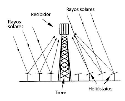
There are concentration collectors of various types (tower, cylindrical-parabolic, Stirling engine).

Nevertheless, all of them have in common that they demand to be equipped, to be efficient, with a tracking system that allows them to remain constantly located in best position to receive the Sun’s rays throughout the day.

One of the drawbacks of most concentration collectors (and especially the cylindrical-parabolic) is that they only take advantage of Sun direct radiation, that is, they only take advantage of solar rays that actually hit their surface. They are not able, on contrary, to capture diffuse solar radiation.

Therefore, they are not convenient in climatic zones that, although they receive an acceptable solar radiation amount, are relatively cloudy. They are only effective in authentically sunny áreas.

Resultado de imagen de colectores solares con concentración

This content was extracted from the Solar Thermal Energy Technical-Commercial Manual and is part of Solar e-learning.

All you need is Sun. All you need is Sopelia.

Honduras Solar Thermal

Honduras is one of the 148 countries in the world with best solar energy generation potential; however, solar thermal energy barely wakes up from several decades of stagnation and at present, its participation is not relevant in the national energy matrix.

Solar thermal energy has a unique competitive potential in the “Sunbelt” countries, characterized by high levels of solar radiation and, often, high prices in energy tariffs.

In Honduras, Choluteca and Valle are the areas with greatest solar energy generation potential, since a maximum annual average of 8.4 hours per day is registered.

February, March and April are the months of greatest solar energy availability in the country, in February there is up to 9.1 sunshine hours on average per year for country southern area.

Other places with high solar potential are in part of Lempira department and Francisco Morazán southern area.

As it happens in almost all Latin American countries, there is no solar thermal energy development according to its enormous potential.Resultado de imagen de solar térmica honduras

Its performance is twice that of photovoltaic solar energy and is the purest expression of distributed generation.

In Honduras, its implantation in residential sector is scarce and there are only isolated cases in commercial and industrial sectors.

An example is the meat plant where a solar thermal system was installed to heat sanitizing water in production area, trays and tables cleaning, pigs blanching, slaughter tools sterilization, sausages cooking and smoking.

Water volume consumed was classified into two types: sanitation and processes.

The advantage of working with the solar thermal system is basically that a volume of preheated water is given to the boiler system.

Initial thermal variation of 20º to 165º C is reduced to a thermal variation of 90º to 165º C, this 70º C difference in temperature is equivalent to the saving (48% in average) provided by solar thermal system as complementary to industrial boiler system.

Another example is the dairy plant in which a solar thermal system was also installed.

In this case, energy efficiency measures were previously applied to reduce hot water consumed volume.

Main one was industrial water guns withstand temperatures higher than 100 ° C implementation.

A thermal solar system with heat pipe collectors was installed, which contributes to sanitization processes and boiler water consumption.

In year highest radiation times, system can cover 97% of monthly boiler water consumed, and 82% on maximum consumption day.

It can also provide up to 90% of total water consumed for production area sanitization.

It can even provide hot water at 42º C for yoghurt preparation.

Solar thermal energy potential in Honduras and in Latin America in general is currently not being exploited.

An exhaustive project survey and analysis allow us to know, a priori, savings will be obtained, initial investment and the generally low maintenance costs.

All you need is Sun. All you need is Sopelia.

Haití Solar Thermal

Devices that capture solar thermal energy range from collectors placed on the roofs to parabolic dishes or solar towers used in large systems that concentrate sunlight, produce heat and generate electricity.

Solar thermal devices are used in countries such as Haiti to:

* Solar water disinfection (SODIS)

By solar light and PET plastic bottles. UV rays exposure eliminates pathogens and bacteria providing a source of clean water and reducing water diseases transmission.

Resultado de imagen de sodis

* Solar Pasteurization

Using a solar cooker and water pasteurization indicators (WAPIs). Solar cooker heats the water and WAPI (small tubes / capsules with melting wax at 65 ° C, temperature with which viruses and bacteria die) indicates when it is suitable for consumption, saving fuel and reducing water diseases transmission.

Resultado de imagen de solar pasteurization

* Solar food dryer

Box with glazed lid and opening + mesh frames. Foods are placed in mesh racks and dried as the sun warms the box. Reduce use of fossil fuels, pollution and post-harvest losses.

Resultado de imagen de solar food dryer

* Solar kitchen

Heat trap boxes, curved concentrators and cooker panel. A device (mirror or reflective metal) concentrates light and heat inside a small cooking area. Reduce reliance on traditional fuels such as wood or coal and reduce indoor pollution.

Resultado de imagen de cocina solar

* Solar water heater

Solar thermal collector + water storage tank. Collector heats the fluid passing through it and heat is stored in the tank. Reduces reliance on traditional fuels; reduces carbon emissions and local pollution.

Resultado de imagen de solar water heater

Constant earthquakes cause many people in Haiti to live outdoor and in very bad conditions.

As they say, “here the sun never fails us.”

However, charcoal is life and scourge of Haitians. Without it, they don´t eat.

97% of the country is deforested. Each person consumes the equivalent of 500 kilograms of wood a year and an average family leaves half of their profits in firewood purchase.

Erosion is the big problem. People cut trees to survive; there is no other way to living.

This country needs a permanent solidarity commitment from international community.

An example of this is solar cooker project for Mont-Organisé.

Devices are based on solar concentration: they generate thermal energy from sunlight that passes through a lens. Energy is stored in a thermal “battery” that maintains heat for 20 hours, and therefore allows cooking at night.

Materials chosen to make the kitchens are sustainable, biodegradable and the device obviously does not need fuel.

Project is developed in collaboration with Italian Microcredit Agency, Federico II Naples University Agrarian Department, Tesla IA SRL and PACNE NGO.

In addition to financing, solar energy expansion to poor people requires a mix of scientific improvements, policy initiatives and collective action to combat climate change and energy access lack.

All you need is Sun. All you need is Sopelia.

Vacuum Tubes Collector

Within group of solar collectors without concentration are the vacuum tubes collectors.

Currently they are the most used.

As was seen in flat collector’s analysis, conversion of radiant energy from the sun to thermal energy leads to radiation, conduction and convection losses that progressively decrease the yield as temperature difference between collector and environment increases.

Improvement provided by vacuum tube collectors is to avoid conduction and convection losses.

If less heat is lost, we will in most cases obtain more yield for same amount of Sun energy.

We will see that this is not always the case and depends on temperature of use.

Vacuum collectors find their main application in intermediate temperature systems (heating, air conditioning, industrial processes, etc.) and in cold places with high differences between collector temperature and the environment.

The vacuum technique used by fluorescent tubes manufacturers has been developed and is the one used by vacuum tube manifolds manufacturers.

Vacuum tube collector systems are based on evacuated tubes.

These are formed by two concentric tubes between which the air has been sucked up producing a vacuum. At one end, both tubes are joined by sealing the vacuum. Inside both tubes are located the different types of absorbers that determine the different systems.

Single evacuated tubes are evacuated tubes, assembled directly with accumulation tank or independently, which may contain only water or water plus antifreeze.

A dark colored layer of absorbent material is located on evacuated tube inner wall.

When solar radiation strikes the absorbent material layer it is transformed into heat and raises the temperature of the fluid that is in contact with it.

The fluid is heated by convection and begins to rise through the tube being replaced by cold fluid which in turn heats up and restarts the process.

This type of vacuum tube offers the advantage of having the aforementioned few heat losses and the disadvantages of being very sensitive to pressure.

Resultado de imagen de colector solar tubos evacuados

U-Pipe vacuum manifolds are used both in individual collectors and in compact solar systems with integrated tank.

Absorber can be placed on tube wall as in evacuated tube case or on an absorbent material sheet.

In any case, absorber is run on its surface by a pipe (preferably copper) through which the fluid raises its temperature in contact with it flows.

U-Pipe tube manifolds have the advantage of being able to adopt both horizontal and vertical position without impairing their performance since tube can rotate on its axis by tilting absorber in the most appropriate way in case the absorber has sheet shape.

Resultado de imagen de colector solar u pipe

Finally, in vacuum tube technology we find heat pipe manifolds.

They employ a mechanism consisting of a closed tube into which a vaporizing fluid (alcohol mixture) of specific properties is introduced.

When sun hits absorber attached to the tube, fluid evaporates and absorbs heat (latent heat). As gas rises above liquid to top of the tube where the cold spot is located. There it liquefies (condenses) and yields its latent heat to the fluid we are interested in heating by falling back to tube bottom by capillarity or gravity.

This process (evaporation – condensation) is repeated for sun’s radiation duration or until collector has reached a very high temperature (around 130 ° C or more).

They have the advantage that each tube is independent being able to change in full system operation. It is highly frost resistant.

Since tubes can also rotate on their axis, it is possible to adopt vertical and horizontal positions as in the case of U-Pipe systems, although in this case generally a minimum tube inclination (between 15º and 20º according to manufacturer) to allow fluid, once liquefied, to fall by gravity.

There are 3 qualities of these collectors:

– Dry union: heat exchange occurs without direct contact between heat transfer fluid and tube, which makes them very suitable in areas with unfavorable water qualities.

– Diode function: heat transfer is always carried out only in one direction, from absorber to heat transfer fluid, and never other way round.

– Temperature limitation: evaporation – condensation cycle takes place as long as vaporizing fluid critical temperature is not reached, thus avoiding uncontrolled temperature rise inside the tubes risks.

Resultado de imagen de colector solar heat pipe

This content was extracted from the Solar Thermal Energy Technical-Commercial Manual and is part of Solar e-learning.

All you need is Sun. All you need is Sopelia.

Flat Plate Solar Collector

Within the solar collectors without concentration we find the flat plate.

They were the most used, but have lost ground in favor of vacuum tube.

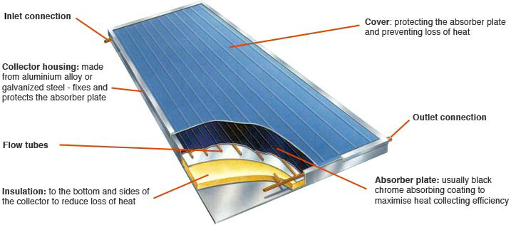
In flat collectors, the collector is located in a rectangular box (housing), whose usual dimensions are between 80 and 120 cm wide, 150 and 200 cm high, and 5 and 10 cm thick (although there are larger models).

Resultado de imagen de cubierta colector solar plano

The face exposed to the sun is covered by a very fine glass, while the remaining five faces are opaque and are thermally insulated.

Inside the box, on the face that is exposed to the sun, is placed a metal plate (absorber).

This plate is attached or welded to a series of conduits through which a heat transfer agent (usually water, glycol, or a mixture of both) flows.

A selective surface treatment is applied to mentioned plate or is simply black painted, to increase its heat absorption.

Flat solar collectors work taking advantage of greenhouse effect (the same principle that can be experienced when entering a car parked in the sun in summer).

After passing through the glass (transparent for wavelengths between 0.3 μm and 3 μm) radiation reaches absorber surface, which is heated and emits radiation with a wavelength between 4.5 μm 7.2 μm, for which the glass is opaque.

Approximately half of this last radiation diffuses to the outside, being lost; but the other half returns inward and thus contributes to absorber surface further heating.

As it passes through the box, the heat transfer fluid heats up and increases its temperature at absorber expense, which temperature will decrease.

The heat transfer fluid then transports that heat energy to where it is desired.

Resultado de imagen de cubierta colector solar plano

The flat solar collector is formed by 4 main elements:

1) Transparent cover: it must possess the necessary qualities (suitable transmission and thermal conductivity coefficients) to provoke the greenhouse effect and to losses reduce; ensuring manifold water and air sealing, in conjunction with housing and joints; do not keep outer surface dirt adhering so that rain easily slips.

2) Absorber: receives the solar radiation and converts it into heat that is transmitted to the heat transfer fluid.

Shapes are diverse: metal plates separated by a few millimeters, a metal plate with welded or embedded tubes or two metal plates with a circuit inside.

Face exposed to sun must capture the largest radiation amount so it is usually black painted or endowed with a selective surface (very absorbent to radiation and with low emissivity).

Paints are cheaper than selective surfaces and have a better overall thermal behavior at near-ambient temperatures, but are marred by ultraviolet radiation continued action and temperature variations between day and night.

Selective surfaces generally have a better behavior and are obtained by several layers superposition (metal and metal compounds) or special surface treatments.

The most modern manufacturing technique is laser welding.

3) Insulation: it is used to reduce thermal losses in absorber rear part that must be of low thermal conductivity. Materials can be glass wool, rock wool, cork, polyethylene or polyurethane.

4) Housing: generally made of aluminum or stainless steel, it protects and supports manifold elements, also allowing manifold anchoring and holding to assembly structure. It must withstand temperature changes (dilatations) without tightness losing and must resist corrosion.

Solar energy wherever you are with Sopelia.